Seal structure of turbo-molecular pump

A technology of turbomolecular pump and sealing structure, which is applied in the direction of pumps, parts of pumping devices for elastic fluids, pump elements, etc. Longer and other problems, to achieve the effect of short axial length

Inactive Publication Date: 2008-01-02
OSAKA VACUUM
View PDF1 Cites 4 Cited by
  • Summary
  • Abstract
  • Description
  • Claims
  • Application Information

AI Technical Summary

Problems solved by technology

[0009] In addition, the above-mentioned sealing structure with the threaded sealing part also has the disadvantage that the required length of the journal shaft part in the axial direction becomes longer, and the length of the rotating shaft of the turbomolecular pump becomes longer.
This poses the problem of increasing the size of the turbomolecular pump

Method used


Image

  • Seal structure of turbo-molecular pump
  • Seal structure of turbo-molecular pump
  • Seal structure of turbo-molecular pump

Examples


Embodiment 1

[0031] Embodiment 1 of the present invention will be described with reference to FIG. 1 and FIG. 3 .

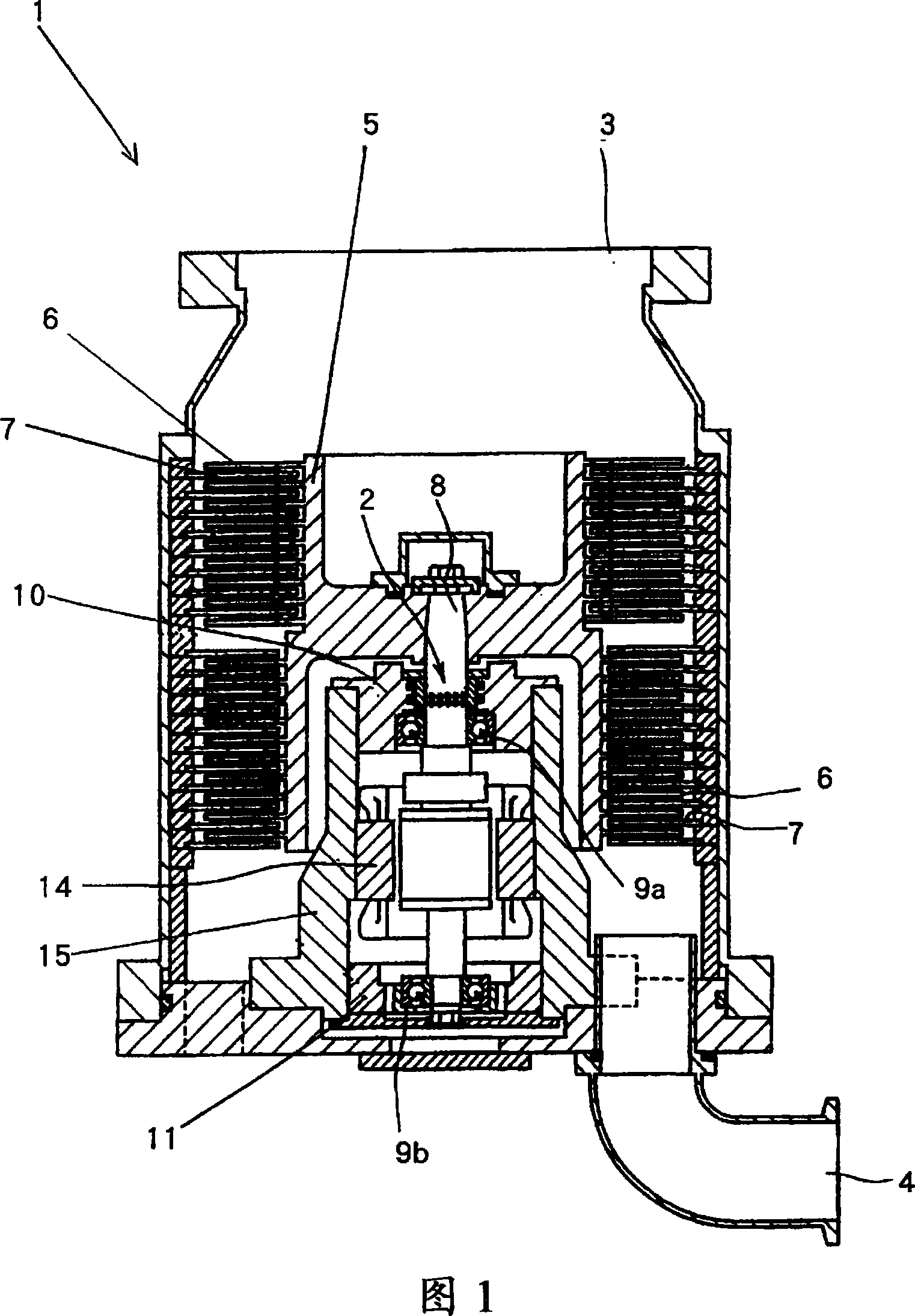
[0032] 1 is a longitudinal sectional view of a turbomolecular pump 1 having a sealing structure according to the present invention, 2 is a sealing structure part described later, 3 is an intake port, and 4 is an exhaust port.

[0033] 5 is a rotor, which has a plurality of rotor blades 6 on the outer periphery, which are radial and multi-layered.

[0034] In addition, 7 is a stator blade.

[0035] A rotating shaft 8 is provided at the center of the rotor 5, and the rotor 5 and the rotating shaft 8 rotate integrally at high speed.

[0036] The above-mentioned rotating shaft 8 is rotatably supported by the stationary members 10, 11 of the housing through oil-lubricated rolling bearings 9a, 9b.

[0037] In addition, 14 is a motor for driving the above-mentioned rotary shaft 8, and 15 is a motor casing.

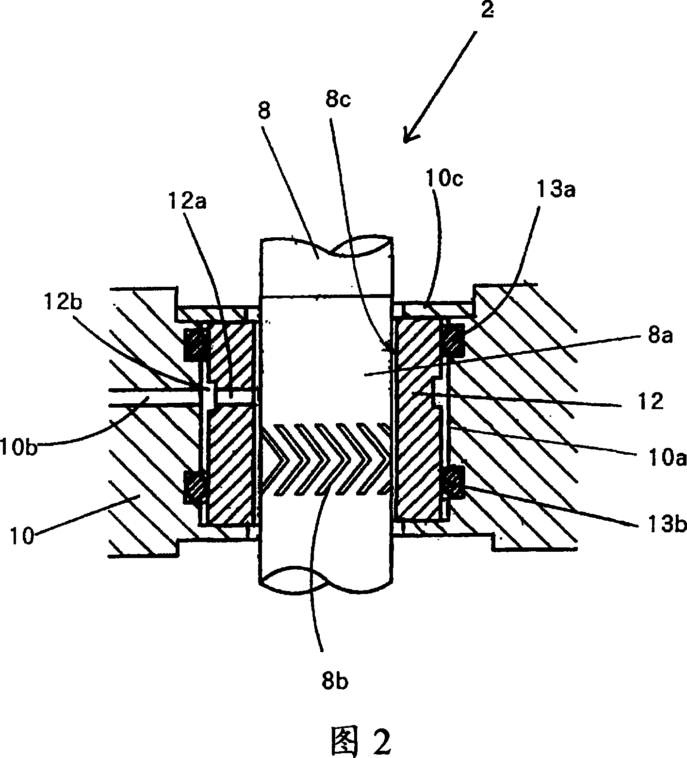
[0038] The specific structure of the above sealing structure part 2 is s...

Embodiment 2

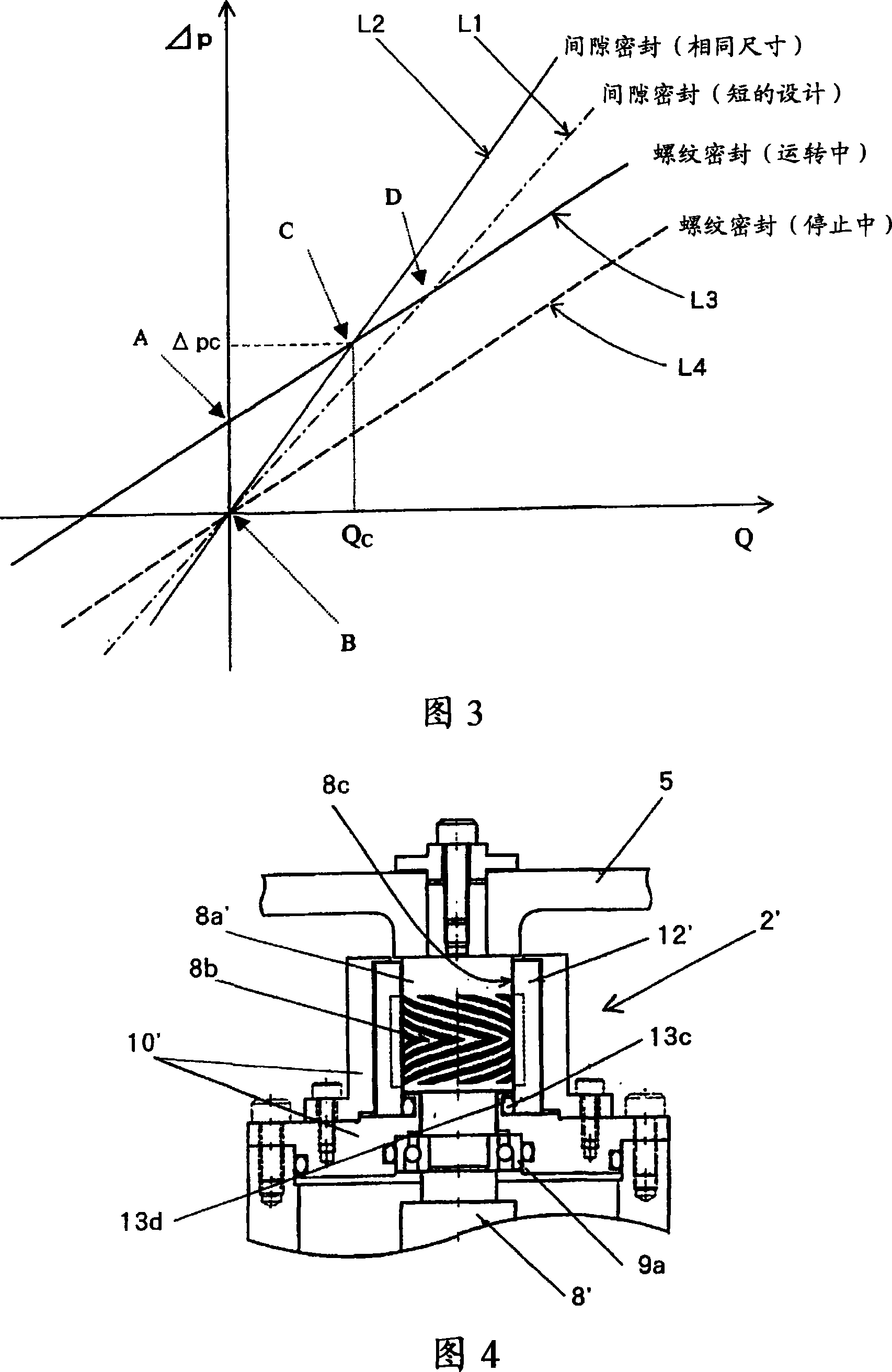
[0069] Next, Embodiment 2 of the present invention will be described with reference to FIG. 4 and FIG. 5 .

[0070] Fig. 4 is a specific schematic diagram of the sealing structure part 2' of the turbomolecular pump of this embodiment.

[0071] In the above-mentioned Embodiment 1, the O-rings 13a and 13b interposed between the stationary member 10 of the housing and the bushing 12 fit into the grooves formed on the stationary member 10 to elastically hold the bushing 12, but in this In the embodiment, the O-ring 13c is provided in contact with the inner peripheral portion of the bushing 12', and the O-ring 13c is inserted into the O-ring groove 13d provided on the stationary member 10' of the turbomolecular pump casing, The above-mentioned bush 12' is elastically held by this O-ring 13c.

[0072] That is, in FIG. 4, a herringbone groove 8b is recessed on the journal shaft portion 8a', and the outer peripheral portion of the journal shaft portion 8a' above the groove 8b (on the...

Embodiment 3

[0077] Embodiment 3 of the present invention will be described with reference to FIG. 6 .

[0078] The sealing structure part 2'' of the third embodiment is a part in which the fixed gap sealing part 5a is added to the sealing structure part 2' of the turbomolecular pump shown in the above-mentioned embodiment 2.

[0079] That is, the formed fixed gap sealing portion 5a has a slight gap between the perforated disc body 5b provided on the upper end portion of the stationary member 10' and the shank 5c of the rotor 5 inserted through the inner peripheral portion of the perforated disc body 5b. gap. Here, the gap for fixing the gap sealing portion 5 a is preferably set within a range of 50 micrometers (μm) to 100 micrometers (μm).

[0080] In addition, the above-mentioned perforated disc body 5b is screwed to the upper end portion of the above-mentioned stationary member 10' via a gasket 5d made of a heat insulating material, so that the heat conduction between the above-mention...


PUM


Abstract

A seal structure of a turbo-molecular pump capable of preventing exhaust gases and dust from invading into the bearing part and the motor part of the turbo-molecular pump and enabling a reduction in the length of a seal part. The seal structure comprises a bush (12) radially swingably fitted to the stationary member (10) of the housing of the turbo-molecular pump (1) and a journal shaft part (8a) rotatably inserted into the inner peripheral part of the bush (12). Herringbone type grooves (8b) are recessed in the outer peripheral part of the journal shaft part (8a) and clearance seal parts (8c) are formed in the journal shaft part (8a) and the bush (12) adjacently to the herringbone type grooves (8b).

Description

technical field [0001] The present invention relates to a sealing structure of a turbomolecular pump which is most suitable for vacuum discharging process gas containing corrosive gas and easily condensed gas and the like. Background technique [0002] As a sealing structure of a turbomolecular pump, the applicant previously proposed the following sealing structure of a turbomolecular pump (refer to Patent Document 1): As shown in FIG. 7, a turbomolecular pump a supporting a rotating shaft through a rolling bearing includes a A cylindrical bushing c fitted into the stationary member b of the casing of the turbomolecular pump a, and a journal shaft portion (journal shaft) rotatably inserted through the inner peripheral portion of the bushing c with a very small gap d. A herringbone groove e and a threaded groove f are recessed on the outer peripheral portion of the journal shaft portion d, and a purge gas is introduced between the bush c and the journal shaft portion d. [0...

Claims


Application Information

Patent Timeline
IPC IPC(8): F04D19/04F04D29/10
CPCF04D29/102F04D19/042F04D29/057
Inventor 大林哲郎井口昌司
Owner OSAKA VACUUM
Why Eureka
Try Eureka