
Speed reducer layout structure used for range-extending type electric vehicle

A technology of layout structure and electric vehicle, which is applied to electric power devices, power devices, control devices, etc., can solve the problems of large size and mass of generators, low energy density of generators, and low speed of generators, and achieve obvious energy saving effect. , the effect of reducing battery usage and high power density

Inactive Publication Date: 2019-11-12
HARBIN DONGAN AUTOMOTIVE ENGINE MFG
View PDF5 Cites 1 Cited by
  • Summary
  • Abstract
  • Description
  • Claims
  • Application Information

AI Technical Summary

Problems solved by technology

However, there are many extended-range electric vehicles at present, and the engine, generator, deceleration device, and electric motor are arranged coaxially, which makes the vehicle length too long and difficult to arrange in the engine room
And the engine is directly connected to the generator, resulting in too low generator speed and low energy density of the generator, resulting in a larger size and mass of the generator

Method used


Image

  • Speed reducer layout structure used for range-extending type electric vehicle
  • Speed reducer layout structure used for range-extending type electric vehicle
  • Speed reducer layout structure used for range-extending type electric vehicle

Examples


specific Embodiment approach 1

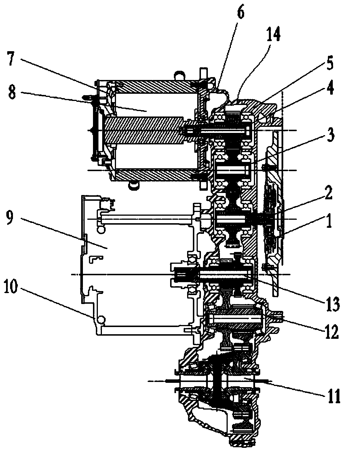
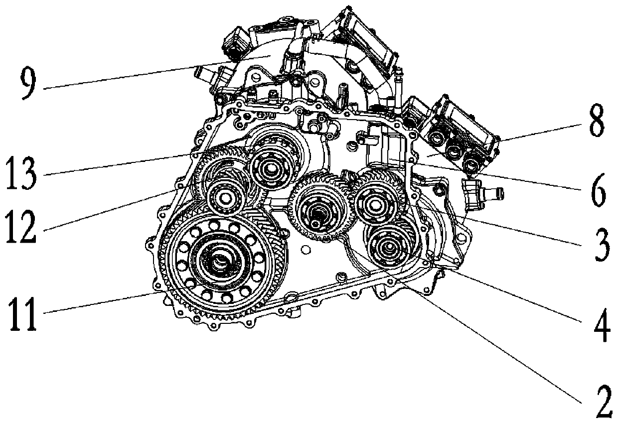
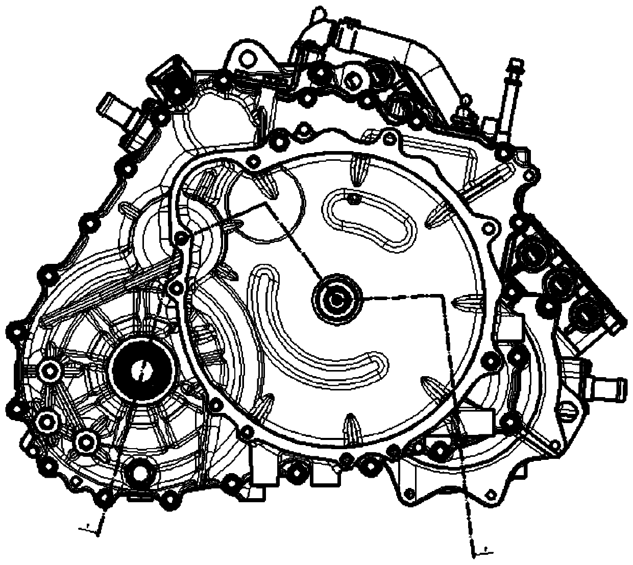
[0019] Specific implementation mode one: combine Figure 1-Figure 3 Describe this embodiment, a reducer layout structure of a range-extended electric vehicle in this embodiment includes a dual-mass flywheel 1, a generator input shaft 2, an idler shaft 3, a generator output shaft 4, a front housing 5, and a rear housing 6. Generator housing 7, generator 8, motor 9, motor housing 10, differential 11, output shaft 12, input shaft 13, engine and dual mass flywheel 1 are connected by bolts, dual mass flywheel 1 and generator The input shaft 2 is connected by a spline, the generator input shaft 2 is meshed with the idler shaft 3 through a gear, the idler shaft 3 is meshed with the generator output shaft 4 through a gear, the generator output shaft 4 is connected with the rotor of the generator 8 by a spline, The electric energy sent by the generator 8 is transmitted to the power battery and the motor 9. The motor 9 is connected to the input shaft 13 through a spline. The input shaft...

specific Embodiment approach 2

[0027] Specific implementation mode two: combination Figure 1-Figure 3 The present embodiment is described. In the reducer layout structure of the range-extended electric vehicle of the present embodiment, cooling channels for cooling the generator 8 and the motor 9 are respectively arranged on the generator housing 7 and the motor housing 10 . In this way, the cooling channels distributed on the generator housing 7 and the motor housing 10 can cool the generator 8 and the motor 9, reduce the heat generated by their work, and improve the working efficiency and service life.


PUM


Abstract

The invention discloses a speed reducer layout structure used for a range-extending type electric vehicle, and belongs to the technical field of electric vehicle speed reducers. The speed reducer layout structure comprises a power generation transmission mechanism, a drive transmission mechanism and a differential mechanism, wherein the power generation transmission mechanism comprises a power generation input shaft, an idle wheel shaft and a power generation output shaft; the drive transmission mechanism comprises a drive input shaft and a drive output shaft; power output by an engine is transmitted into the power generation transmission mechanism through dual mass flying wheels, and rotation speed is increased by the power generation transmission mechanism through a gear wheel of each axle, so that a power generator is driven to generate power in a high-efficiency area, and therefore, electric power is provided to a whole vehicle power battery and a drive motor; power generated by the drive motor is transmitted to the differential mechanism through secondary speed reduction of the drive transmission mechanism, and the differential mechanism is used for transmitting power to wheels to drive the whole vehicle to travel. The power transmission mechanism is more compact and simpler in structure, is convenient in assembly, and effectively overcomes the defects that an existing electric vehicle is low in endurance mileage and is high in cost due a too great power battery.

Description

technical field [0001] The invention relates to a range-extended speed reducer, which belongs to the technical field of range-extended electric vehicle speed reducers. Background technique [0002] With the increasing global greenhouse effect, the frequent occurrence of smog events in various places, and the increasing number of automobiles, automobile exhaust has become an important cause of climate change. Therefore, electric vehicles have become a very potential development of automobiles. direction. [0003] At present, due to the limitation of battery storage capacity of pure electric vehicles, the weight of the battery is heavy, so the weight of the whole vehicle is large, and it does not save electricity; there are many batteries, high specific energy, high risk, and high risk of spontaneous combustion; the battery consumption is large, and the price of the vehicle is high. , and the battery life is low, and the replacement cost is high. In order to increase the cru...

Claims


Application Information

Patent Timeline
IPC IPC(8): B60K17/04B60K17/16B60K1/00
CPCB60K1/00B60K17/04B60K17/165
Inventor 于忠贵姚书涛贾海涛周章遐张晓冬王墨李承鹏孙楚萍张雪峰袁志强刘佩龙谭望毕崇盛
Owner HARBIN DONGAN AUTOMOTIVE ENGINE MFG
Learn More