
Mechanism capable of simultaneously performing circumferential rotation and axial movement

A technology of axial movement and inner rotating shaft, applied in the directions of engine components, mechanical equipment, fluid pressure actuating devices, etc., can solve the problems of large relative sliding amount, difficult sealing, small application range, etc., and achieve short axial length, Good sealing effect and the effect of reducing leakage

Pending Publication Date: 2020-02-04
ZHEJIANG CHENGXIN PHARMA & CHEM EQUIP
View PDF2 Cites 2 Cited by
  • Summary
  • Abstract
  • Description
  • Claims
  • Application Information

AI Technical Summary

Problems solved by technology

Although this structure is more compact than the reduction and telescopic mechanism of the sizing machine, because the rotary cylinder can only provide limited rotary motion within the stroke of the rotary piston, it cannot provide continuous one-way rotation like a motor, and the scope of application is small , and in this structure, the telescopic piston rod must not only rotate relative to the telescopic cylinder body, but also move axially relative to the telescopic cylinder body, resulting in a large relative sliding amount between the telescopic piston rod and the telescopic cylinder body, that is, both The amount of friction between them is large, the sealing is difficult, and oil leakage is prone to occur

Method used


Image

  • Mechanism capable of simultaneously performing circumferential rotation and axial movement
  • Mechanism capable of simultaneously performing circumferential rotation and axial movement
  • Mechanism capable of simultaneously performing circumferential rotation and axial movement

Examples


Embodiment Construction

[0024] The following are specific embodiments of the present invention and in conjunction with the accompanying drawings, the technical solutions of the present invention are further described, but the present invention is not limited to these embodiments.

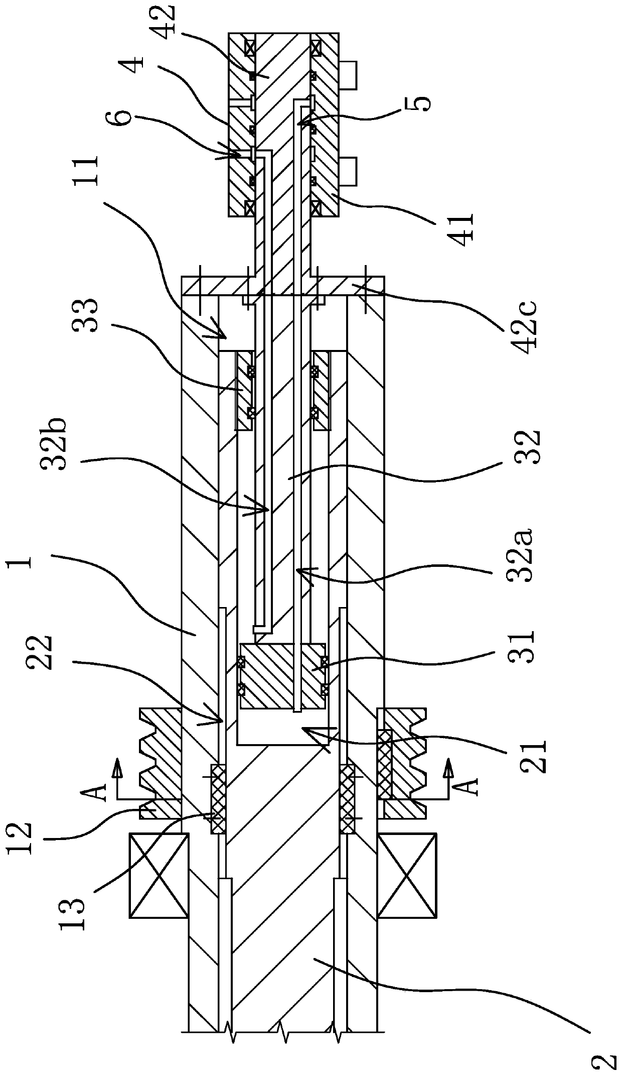
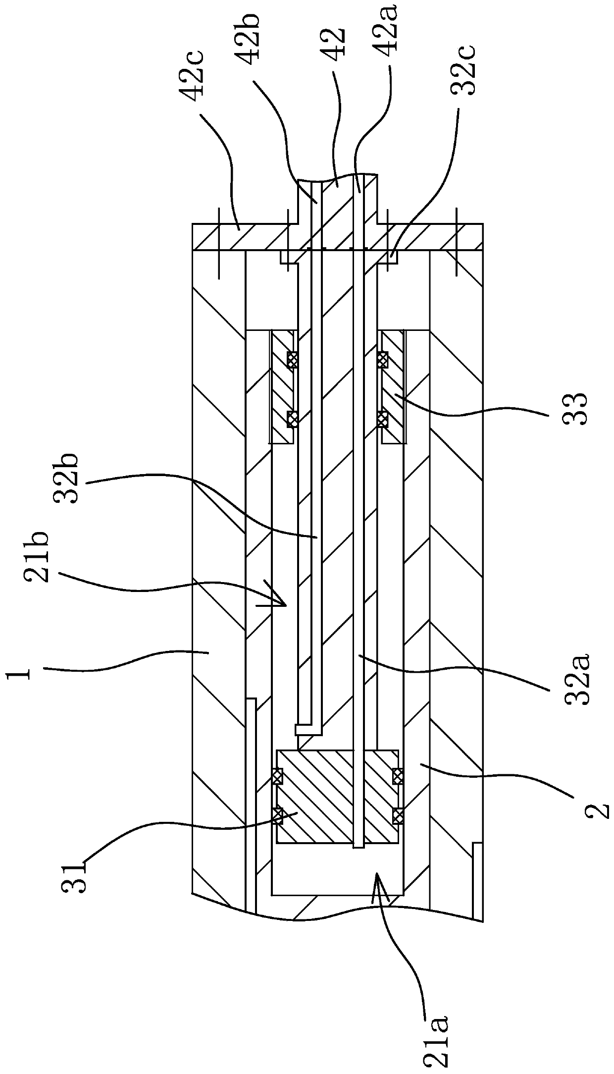
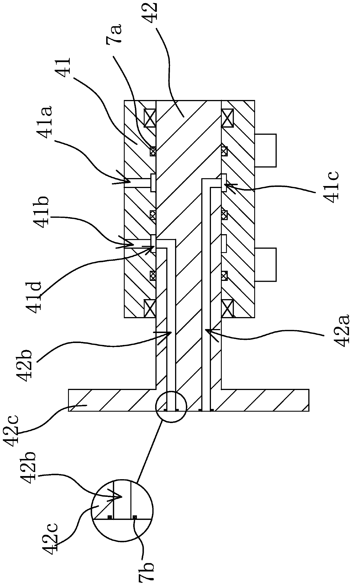
[0025] Such as figure 1 , figure 2As shown, a mechanism that can simultaneously perform circumferential rotation and axial movement includes an outer shaft 1 and an inner shaft 2. The outer shaft 1 is a cylindrical structure provided with a central hole 11 along the axis, and the inner shaft 2 passes through a key. Fitted in the central hole 11, one end of the inner rotating shaft 2 is axially opened with a blind hole 21, the blind hole 21 is provided with a piston 31 and a piston rod 32 connected with the piston 31, the piston 31 separates the blind hole 21 to form a second One oil chamber 21a and the second oil chamber 21b, the end of the piston rod 32 away from the piston 31 protrudes out of the inner shaft 2 and is c...


PUM


Abstract

The invention provides a mechanism capable of simultaneously performing circumferential rotation and axial movement, and belongs to the technical field of machinery. The mechanism solves the problemsthat an existing mechanism capable of simultaneously rotating and axially moving is large in axial dimension, inconvenient to install and poor in sealing effect. The mechanism comprises an outer rotating shaft and an inner rotating shaft arranged in a central hole in a matched penetrating mode through a key, wherein a blind hole is formed in one end of the inner rotating shaft, a piston is slidably connected in the blind hole, a hydraulic rotating joint is connected to the outer end of a piston rod, the hydraulic rotating joint comprises an outer cylinder body and a core shaft rotationally connected in the outer cylinder body and fixedly connected with the piston rod, one end of the core shaft is provided with a sealing disc coaxially arranged, the outer end of the piston rod is provided with an annular convex edge, the sealing disc is fixedly connected with the end surface of one end of and the outer rotating shaft coaxially and seals the central hole, the annular convex edge is arranged coaxial with the sealing disc, and the end surface of the annular convex edge is attached to and is fixedly connected with the end surface of the sealing disc. The mechanism has the advantages that the overall length is shorter, the installation adaptability is better, the abrasion and the oil leakage are not prone to occur, and the sealing effect is better.

Description

technical field [0001] The invention belongs to the technical field of machinery, and relates to a mechanism capable of simultaneously performing circumferential rotation and axial movement. Background technique [0002] In the field of machinery, it is sometimes encountered that some mechanisms need to be able to realize both circumferential rotation and axial movement. In order to realize the above two actions, two driving sources are generally required to be applied to the same rotating shaft at the same time, resulting in a relatively complicated structure and relatively difficult design. [0003] For example, a Chinese patent application (application number: 201520870169.2) discloses a deceleration telescopic mechanism of a sizing machine with a rotary joint to realize the above-mentioned action. The spline shaft, the coupling connected to the output end of the spline shaft, and the piston rod used to drive the spline shaft to expand and contract in the main shaft, the...

Claims


Application Information

Patent Timeline
IPC IPC(8): F15B15/08F15B15/14F15B15/20F16J7/00
CPCF15B15/08F15B15/1423F15B15/1433F15B15/1457F15B15/149F16J7/00
Inventor 郑钦元陈俊嘉陈仁贤
Owner ZHEJIANG CHENGXIN PHARMA & CHEM EQUIP
Learn More