
Electric vacuum booster brake device and control method thereof

A technology of vacuum boosting and braking device, which is applied in braking transmission device, circuit device, battery circuit device, etc., can solve the problems of frequent engine start and stop, complex vehicle controller algorithm, etc.

Inactive Publication Date: 2008-01-09
CHERY AUTOMOBILE CO LTD
View PDF0 Cites 5 Cited by
  • Summary
  • Abstract
  • Description
  • Claims
  • Application Information

AI Technical Summary

Problems solved by technology

In a hybrid vehicle equipped with a traditional vacuum booster, the hybrid controller needs to judge the vacuum pressure to control whether the engine can be automatically stopped. When the engine is in the state of automatic shutdown, the hybrid control device needs to continue to monitor the vacuum pressure. The size is used to control whether to request the automatic start of the engine. Therefore, the algorithm of the hybrid vehicle controller is complex, and the engine starts and stops frequently.

Method used


Image

  • Electric vacuum booster brake device and control method thereof
  • Electric vacuum booster brake device and control method thereof

Examples


Embodiment Construction

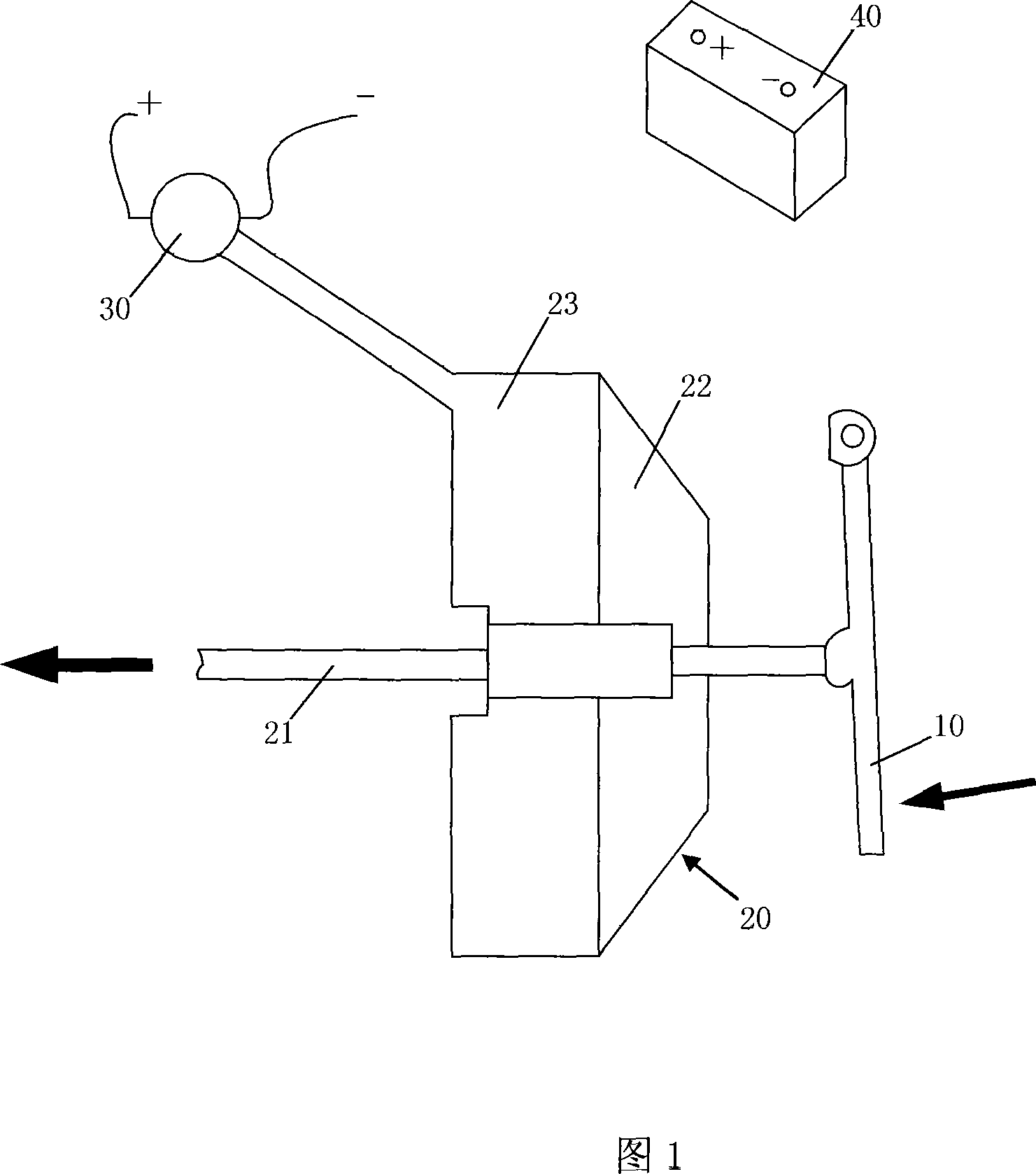
[0015] 1, the electric vacuum booster brake device includes an electric vacuum booster 20 connected to the brake pedal 10, the output rod 21 of the electric vacuum booster 20 is connected to the master brake cylinder, and the electric vacuum booster 20 is provided with a spacer Plate, one side of the partition is a high-pressure gas chamber 22 equal to atmospheric pressure, and the other side is a low-pressure gas chamber 23 connected to a vacuum pump 30 and evacuated gas, the driving power of the vacuum pump 30 is connected to the vehicle 12V power supply battery 40 . In the electric vacuum booster 20, the reaction force mechanism is arranged between the input rod and the valve cylinder and the output rod 21, the valve cylinder and the booster piston are connected into one body, and the valve piston is installed on the input piston connected to the input rod, And the reaction force mechanism can slide forward relative to the input piston from a predetermined retracted positio...


PUM


Abstract

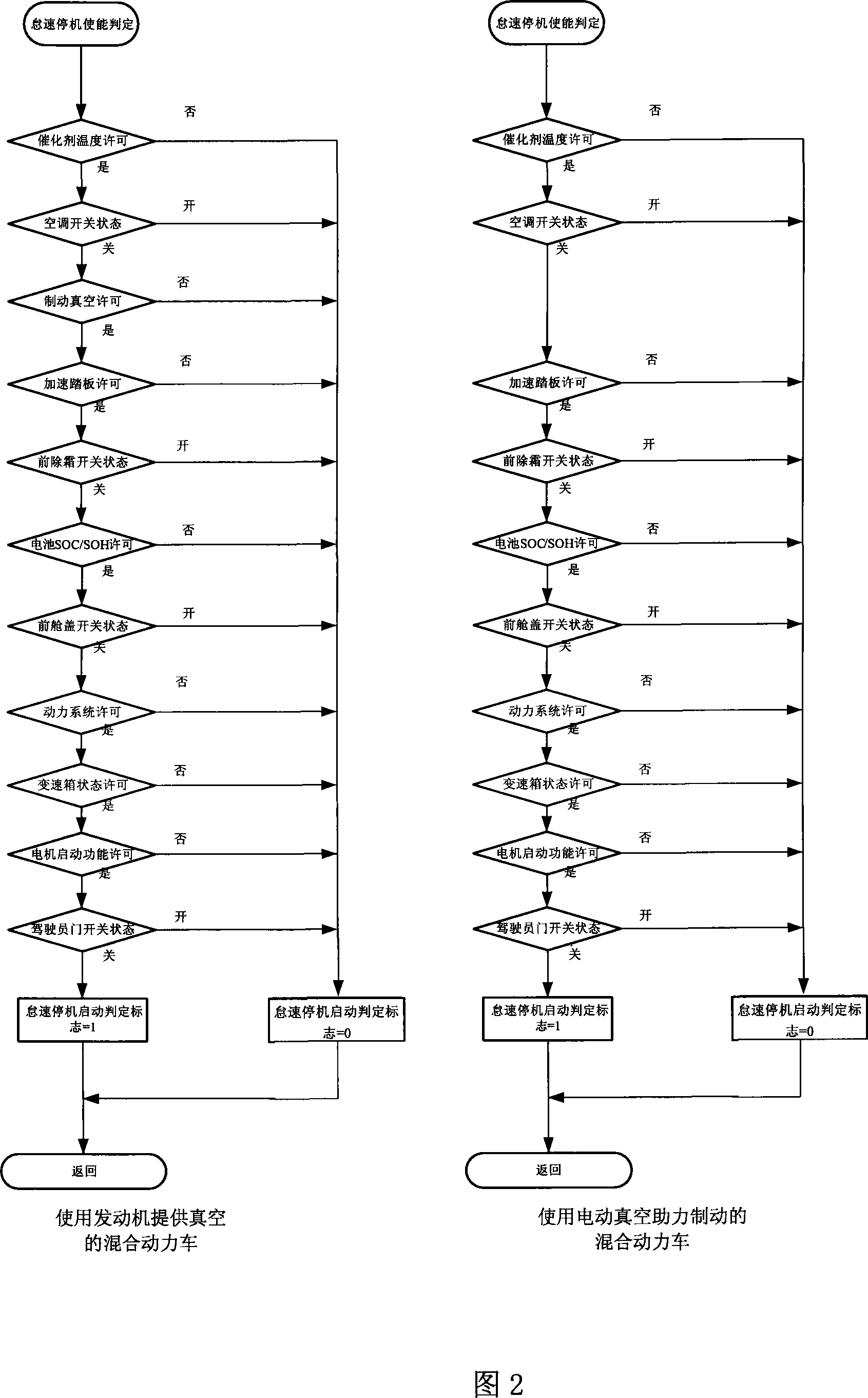
The present invention relates to one kind of electric vacuum boosted brake device suitable for use in a mixed power automobile and its control method. The electric vacuum boosted brake device includes one electric vacuum booster, one vacuum pump, and one drive power source connected to the 12 V automobile battery. Its control method monitoring the charge state of the 12 V automobile battery and the enable or disable state of the automatic engine on-off function, controlling the charging to the battery, monitoring the brake vacuum degree indirectly by means of detecting the SOC and SOH state of the battery, and judging whether to enable the automatic engine on-off function.

Description

technical field [0001] The invention belongs to an electric vacuum booster braking device and a control method for a hybrid vehicle. Background technique [0002] Since the 1990s, major automobile companies in Japan, the United States, and Europe have begun to develop hybrid vehicles. Since Toyota of Japan first launched a hybrid car in 1997, major car companies including Honda, General Motors, Ford, D-C and French Citroen have all launched or developed product cars or concept prototypes. Experts believe that in the next ten years, there may be 40% of the cars will use hybrid technology, hybrid vehicles have a huge development prospect. [0003] Generally, hybrid electric vehicles have an automatic start-stop function. When idling, such as waiting for a red light at an intersection, the engine will be automatically stopped to save fuel and reduce emissions. However, in such an occasion, the vehicle is required to be restarted quickly to avoid the vehicle lingering for too ...

Claims


Application Information

Patent Timeline
Patent Type & Authority Applications(China)
IPC IPC(8): B60T13/52H02J7/14H01M10/44B60W20/00B60W20/15
CPCY02E60/12Y02T10/7005Y02E60/10Y02T10/70
Inventor 邹海斌尚斌
Owner CHERY AUTOMOBILE CO LTD
Learn More