
Anti-theft well cover with magnetic lock

A manhole cover and magnetic lock technology, applied in building locks, water conservancy projects, artificial islands, etc.

Inactive Publication Date: 2008-01-09
夏都
View PDF0 Cites 6 Cited by
  • Summary
  • Abstract
  • Description
  • Claims
  • Application Information

AI Technical Summary

Problems solved by technology

[0003] The present invention provides a kind of existing structural shape and size of all manhole covers in production and in use, which can overcome the difficulties faced by the aforementioned various schemes, and can be used in the manufacture of new manhole covers, and can be used in The transformation technology of all kinds of manhole covers, relying on this technology, can solve the anti-theft problem of all kinds of manhole covers comprehensively, effectively and economically

Method used


Image

  • Anti-theft well cover with magnetic lock
  • Anti-theft well cover with magnetic lock
  • Anti-theft well cover with magnetic lock

Examples


Embodiment Construction

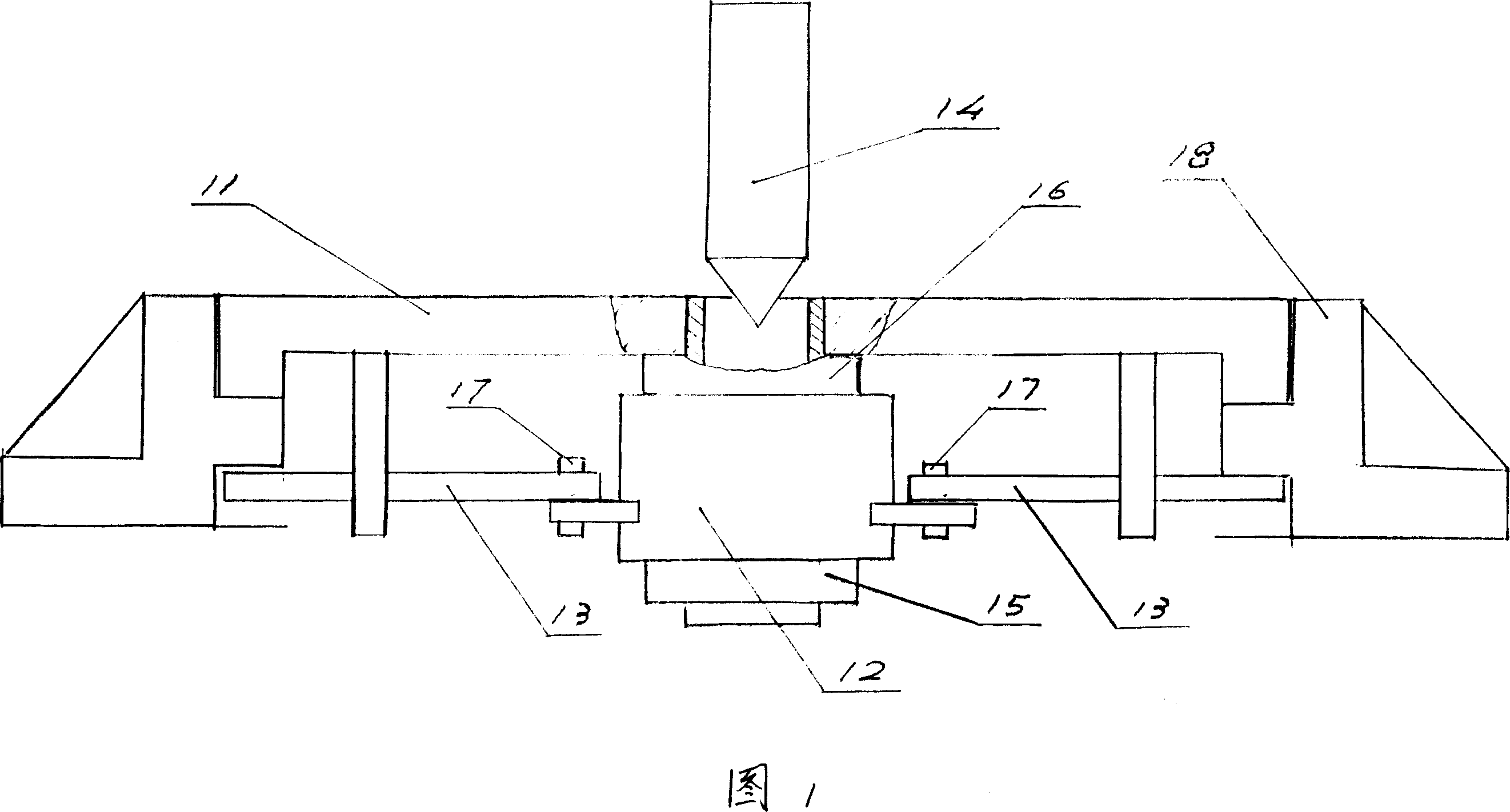
[0017] The present invention will be further described below in conjunction with the accompanying drawings and embodiments.

[0018] The anti-theft well cover with magnetic lock of the present invention (see Fig. 1) is made up of four major parts such as well cover assembly 11, magnetic servomotor 12, locking bar 13 and magnetic bar 14.

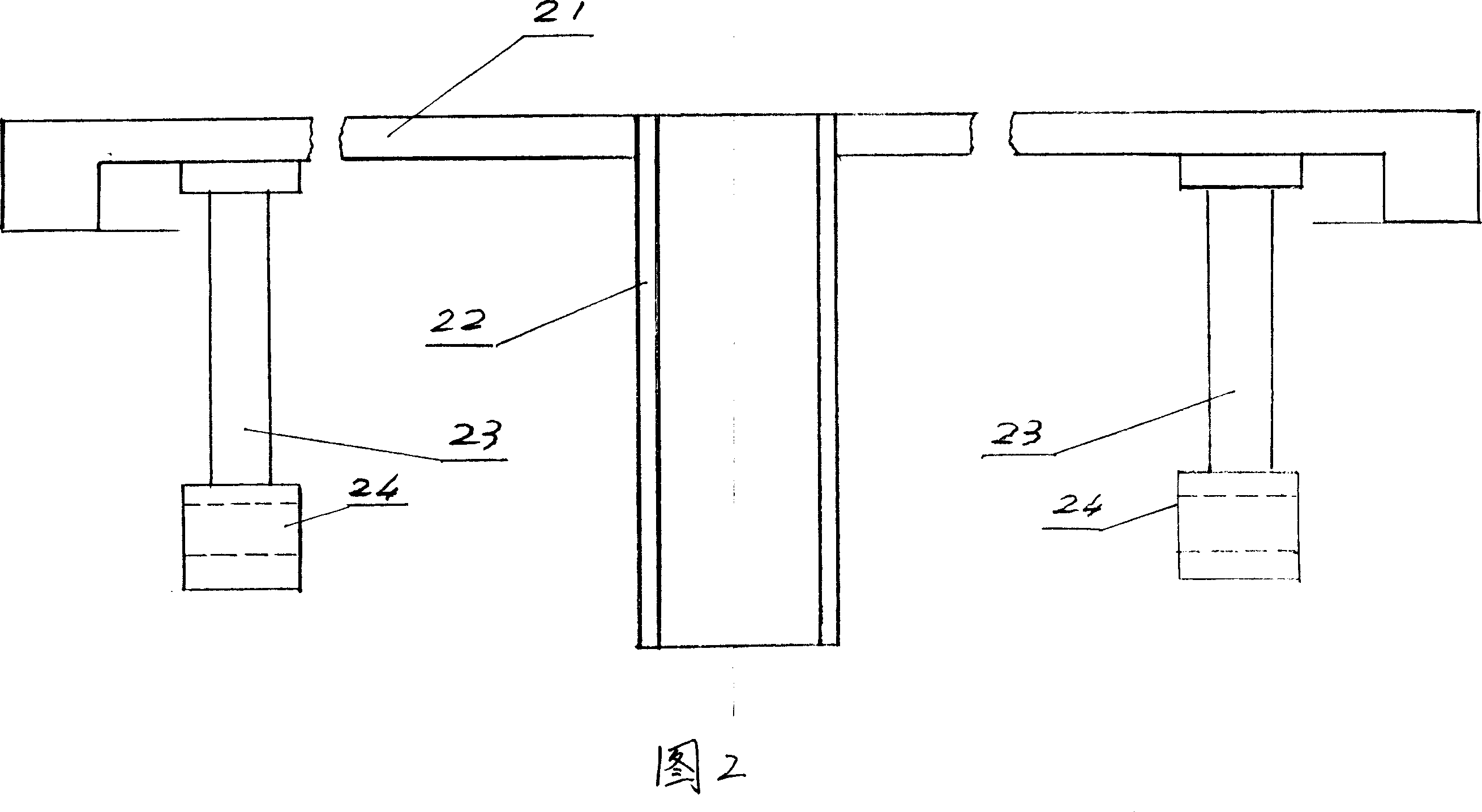
[0019] Well cover assembly (see Fig. 2) is made up of well cover 21, spacer tube 22 and locking rod support rod 23.

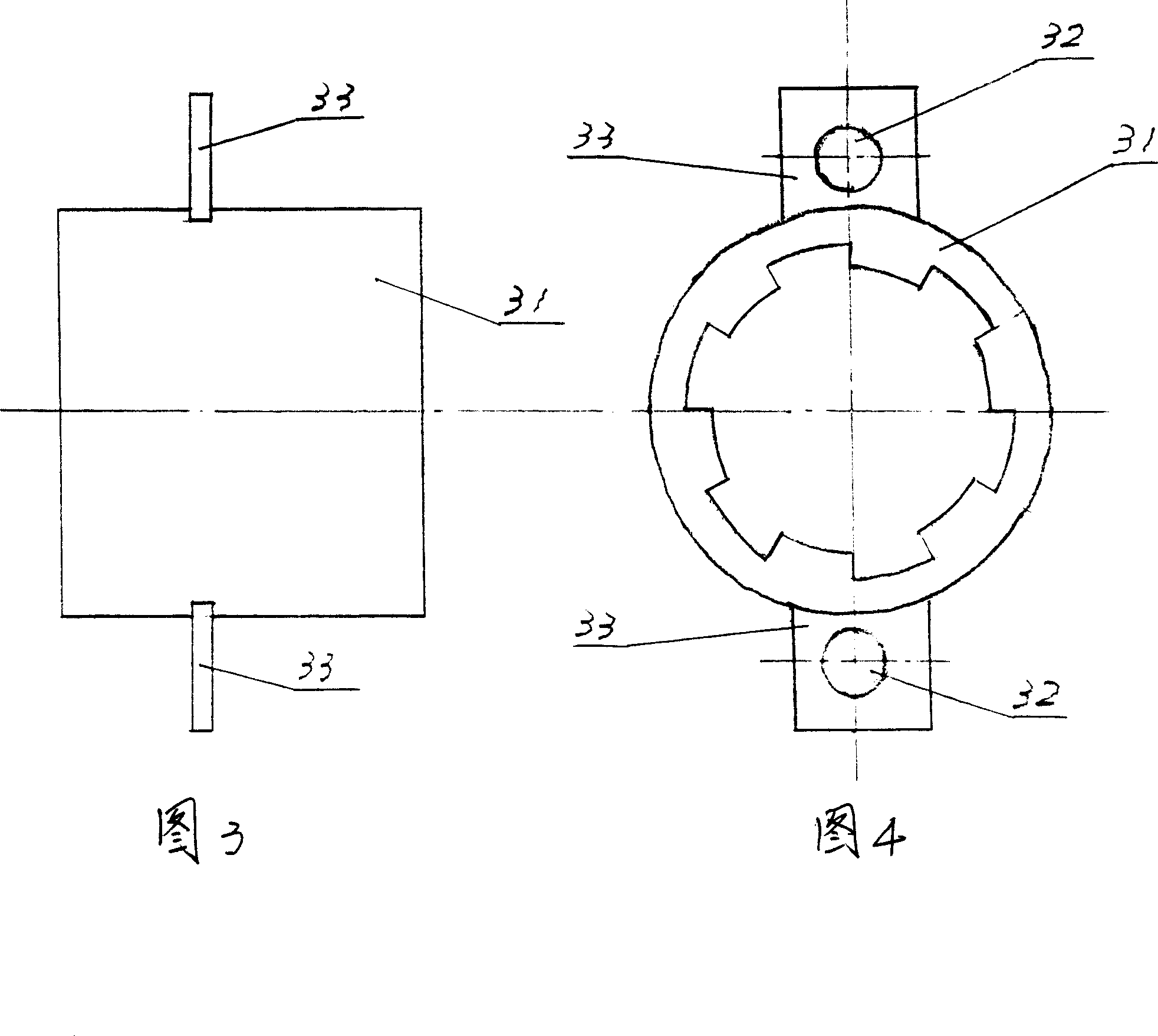
[0020] There is a through hole in the middle part of the well cover 21, and there is a section of the finite length hollow tube in the hole, which is the isolation cylinder 22. One end of it connects with well cover 21 by welding, riveting, screw after directly or after loading onto flange, does not expose the outer surface of well cover 21. The other end protrudes from the inner surface of the well cover 21 . On the inner surface of the well cover 21, relative to the central axis of the isolation cylinder 22, on a larger di...


PUM


Abstract

This is a magnetic locking technology for well cover without any change to the shape and size of existing ones. This technology prevents stolen of well cover.

Description

technical field [0001] The invention belongs to the anti-theft structure category of various road surface well covers widely used in municipal engineering, in particular the well covers with magnetic locks. Background technique [0002] There are a large number of underground buildings in municipal engineering, which are used to lay power cables, communication cables and optical cables, water supply pipelines and accessories, reclaimed water pipelines and accessories, heating pipelines and accessories, oil pipelines and accessories... These underground buildings need to be provided with ground exits at certain distances for engineering construction and maintenance personnel to enter and exit. Each exit needs to be covered to protect the safety of underground facilities and the safety of pedestrians and vehicles on the ground. However, the manhole cover is often in danger of being stolen. Once the manhole cover is stolen, the safety of underground facilities and pedestrians ...

Claims


Application Information

Patent Timeline
IPC IPC(8): E02D29/14E05B65/00
Inventor 夏都
Owner 夏都
Learn More