Display panel test fixture and test method

A technology of display panels and test fixtures, which is applied in the direction of electronic circuit testing, measuring electricity, measuring devices, etc., can solve the problems of inability to quickly change test specifications, and achieve the effect of rapid adaptation

Active Publication Date: 2008-01-09
AU OPTRONICS CORP
View PDF0 Cites 17 Cited by
  • Summary
  • Abstract
  • Description
  • Claims
  • Application Information

AI Technical Summary

Problems solved by technology

[0004] In view of the problem that the testing machine of the display panel in the prior art cannot quickly change the test specification, the technical problem to be solved by the present invention is to provide a test fixture and a test method for the display panel, which can test display panels of different specifications arbitrarily.

Method used


Image

  • Display panel test fixture and test method
  • Display panel test fixture and test method
  • Display panel test fixture and test method

Examples


Embodiment Construction

[0028] The above description of the content of the present invention and the description of the following embodiments are used to demonstrate and explain the principle of the present invention, and to provide further explanation of the claims of the present invention.

[0029] The detailed features and advantages of the present invention will be described in detail in the following embodiments. The content is sufficient to enable anyone familiar with the relevant art to understand the technical content of the present invention and implement it accordingly, and according to the content disclosed in this specification, claims and drawings. Anyone who is familiar with related art can easily understand the related purpose and advantages of the present invention.

[0030] In order to have a further understanding of the purpose, structure, features and functions of the present invention, a detailed description is now provided in conjunction with the embodiments.

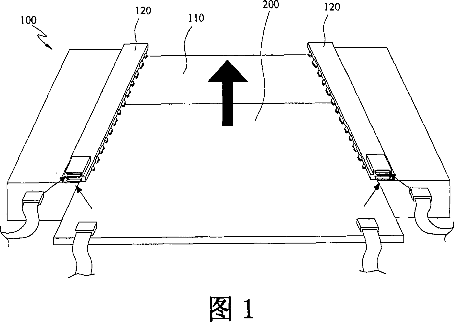
[0031] Referring to FI...


PUM


Abstract

The invention relates to a display panel test assistant tool and method, and the tool comprises a plate piece and probes beside the plate piece, where these probes at least include plural first probes to contact signal contact points of first tested panel with first standard and transmit first test signal to them; and plural second probes to contact signal contact points of second tested panel with second standard and transmit second test signal to them. Therefore, the test assistant tool is selectably used to test display panels of different standards.

Description

Technical field [0001] The present invention relates to testing display panels, in particular to a testing fixture and testing method that can test display panels of different specifications. Background technique [0002] After the display panel is made, a test machine must be used to generate a test signal and send it to the display panel to confirm whether the display panel can operate correctly. Since the display panel that has just been manufactured by the production line has not been equipped with signal cables or electrical connectors, the test machine must feed test signals to the display panel through a test fixture with probes. The test fixture uses the probe to contact the signal contact (Contact Pad) exposed on the edge of the display panel to achieve electrical connection, and transmit the test signal to the display panel to be tested. [0003] The size of the display panel of different specifications is not the same, and the number of signal contacts on the display p...

Claims


Application Information

Patent Timeline
Patent Type & Authority Applications(China)
IPC IPC(8): G01R31/00G01R31/28G01R1/073G09G3/00
Inventor 林宪杰
Owner AU OPTRONICS CORP
Why Eureka
Try Eureka