Banknote treatment device

A banknote processing device and technology for banknotes are applied in banknote processing equipment, coin accepting devices, thin material processing, etc., and can solve problems such as banknotes being stuck and unable to be detected.

Inactive Publication Date: 2008-01-09
OKI ELECTRIC IND CO LTD
View PDF2 Cites 27 Cited by
  • Summary
  • Abstract
  • Description
  • Claims
  • Application Information

AI Technical Summary

Problems solved by technology

[0007] That is, there is the following problem: although the sensors arranged on the transport path can detect the oblique travel, overlapping conveyance, and lateral deviation of the banknotes, they cannot detect, for example, the bending that occurs in the banknotes due to being folded in four. The bent banknotes are transported as they are, and as a result, the bent parts of the banknotes collide with the guides arranged on the transport path or the switching blades for switching the transport direction, causing malfunctions such as banknote jamming

Method used


Image

  • Banknote treatment device
  • Banknote treatment device
  • Banknote treatment device

Examples


Embodiment

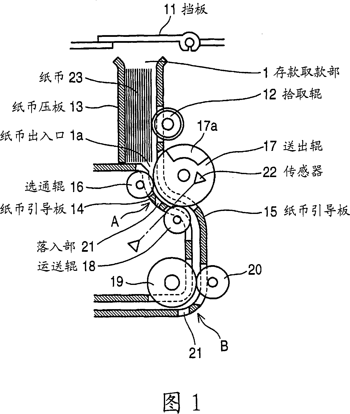
[0028] First, an overall description of the device will be given.

[0029] Fig. 13 is a schematic diagram showing the internal structure of the banknote handling device, and the banknote deposit and withdrawal device will be described as an example here.

[0030] In the figure, 1 denotes a deposit and withdrawal unit (paper money input unit) for allowing the user to insert banknotes or spit out banknotes to the user to withdraw money, and 2 indicates identification for identifying and counting banknotes during deposits and withdrawals. Sections 3a to 3d represent temporary storage sections for temporarily storing banknotes that have been authenticated as genuine banknotes that can be deposited by the identification section 2 .

[0031] 4a-4d have shown the banknote accommodating part arrange|positioned in parallel in the up-down direction, and the temporary storage part 3a-3d is provided corresponding to this banknote accommodating part 4a-4d.

[0032] Here, the banknote stor...


PUM


Abstract

The invention provides a paper money processor. When a bill collection part deliveries fold bill, the paper money processor can immediately and reliably detect the fold bill. When the bill (23) of bending part (23a) with high possibility of blocking bill on the bill deliverying path is sent from bill collection part (1), the one side of left and right of the bending part (23a) of bill (23) strikes the end face (21b) of downstream at the bill delivery direction of drop-in part (21) to make the bill (23) obliquely circulate and a sensor (22) arranged at the downstream of drop-in part (21) detects the obliquely circulation, or monitors and detects the arrival time to the sensor (22).

Description

technical field [0001] The present invention relates to a banknote handling device used in an automatic transaction machine (ATM) or the like, and particularly relates to a structure for detecting bent banknotes to prevent deposit banknotes from being jammed. Background technique [0002] Conventional banknote processing devices are installed in ATMs and the like as banknote deposit and withdrawal devices. ATMs are installed in business stores such as financial institutions, and transactions such as cash deposits and withdrawals are performed. The banknotes inserted into the deposit withdrawal unit (banknote insertion unit) are separated one by one and fed into the transport path (for example, refer to Patent Document 1). [0003] And the following technology is proposed. When transporting the separated banknotes, sometimes the banknotes are inclined at a large inclination angle, or the banknotes are released in a state of overlapping two or more sheets, resulting in overlap...

Claims


Application Information

Patent Timeline
Patent Type & Authority Applications(China)
IPC IPC(8): G07D11/00B65H3/06B65H7/06
CPCG07D11/16G07D11/237G07D2211/00G07F19/201
Inventor 越田嘉范
Owner OKI ELECTRIC IND CO LTD
Why Eureka
Try Eureka