

Escaping device for building
An escape device and building technology, applied in the field of escape devices, can solve the problems of insufficient safety factor, fast landing speed, inconvenient operation, etc., and achieve the effects of safe and stable sliding process, stable descending speed, and easy operation.
Inactive Publication Date: 2010-11-10
姜望轩
View PDF0 Cites 0 Cited by
- Summary
- Abstract
- Description
- Claims
- Application Information
AI Technical Summary
Problems solved by technology
The purpose of the present invention is to provide an improved escape device for buildings, which can overcome the shortcomings of the existing high-rise temporary escape devices, such as insufficient safety factor, too fast landing speed, and inconvenient operation.
Method used
View moreImage
Smart ImageViewing Examples

Examples
Embodiment Construction
Login to View More PUM
 Abstract
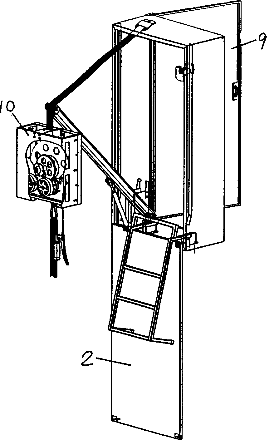
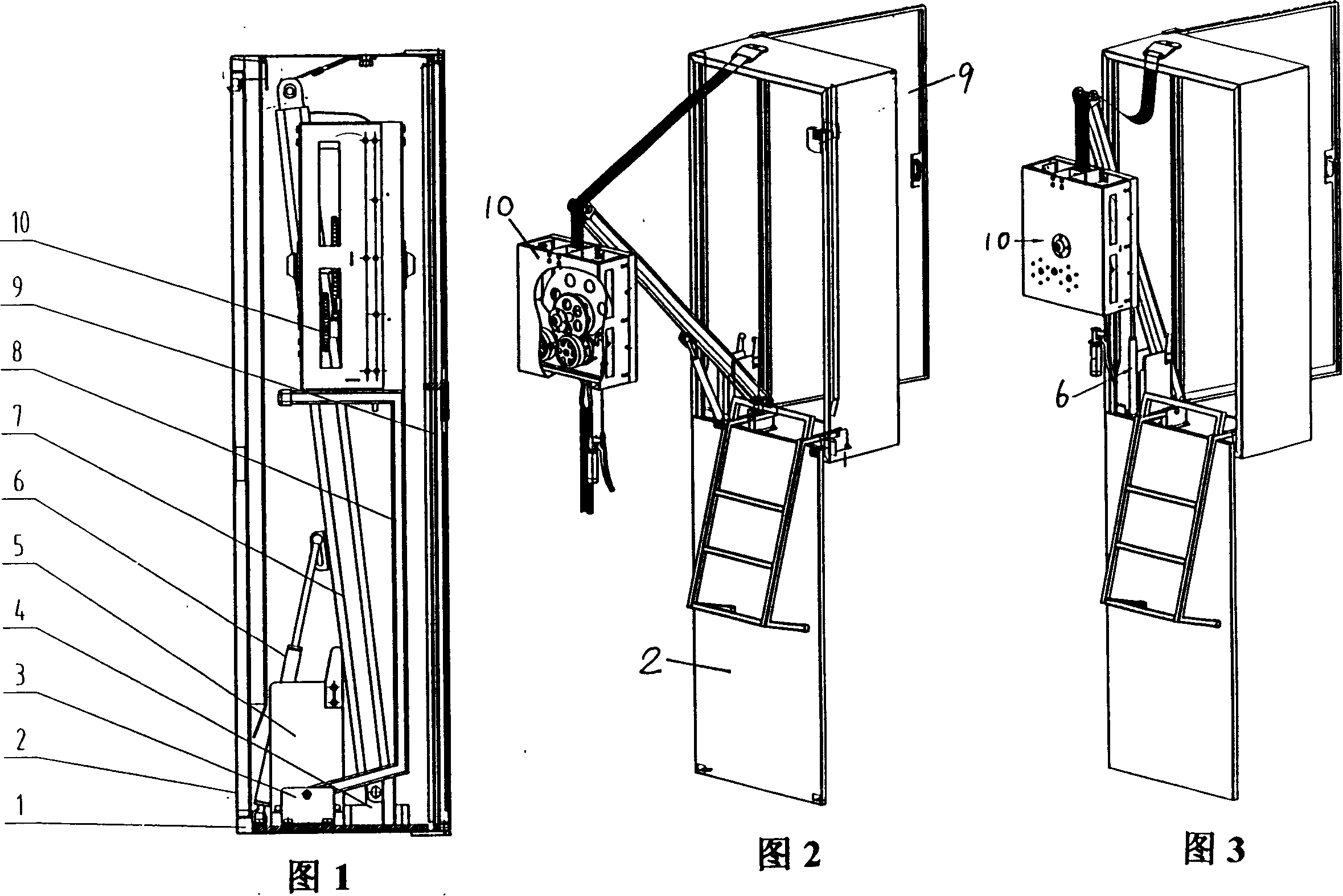
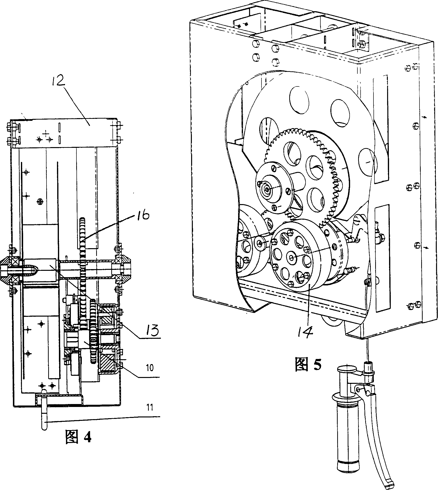
The invention relates to an escaping device used for a building, which is characterized in that: a escape capsule is formed by a shell body of a frame and a front and a back port arranged on two side faces of the shell body, a stay bar and a ladder are arranged inside the escape capsule, the stay bar and one end of the ladder are connected with the bottom part of the escape capsule and the connection is rotatable, a gas-filled support is arranged between the stay bar and the bottom part of the escape capsule, a belt rope and a safety belt are arranged on the escaping stable-descending device,the top part of the belt rope has a fork, one end of the fork is connected fixedly with the top part of the escape capsule, and the other end of the fork is connected fixedly with the top part of thestay bar. When in use, the escape capsule is arranged on the wall of the building, people need to open the front port of the escape capsule to enter the escape capsule, and then push open the back port to push out the escaping ladder and take out the escaping stable-descending device and the stay bar for escaping, the person need to tie the safety belt on the waist and hang the safety hook well and then stand on the ladder, the descending of the stable-descending device can be controlled by the clasping and releasing of the handle, then the stability of the initial speed can be guaranteed, sothe whole descending process is safe and stable.
Description
An escape device for a building Technical field: The invention relates to the technical field of high-altitude rapid descent, in particular to an escape device for buildings from inner walls to outer walls. Background technique: Temporary escape devices for high-rise buildings currently on the market are usually divided into those used by a single person (such as ropes, hanging baskets, etc.) In the process of falling, these devices often do free fall, and the user cannot control the speed of the descent. This will not only aggravate the panic of the user, but also have a large risk factor, which brings great danger to emergency escape. It is very inconvenient. At the same time, this kind of equipment is also widely used in the field of cleaning the outer walls of high-rise buildings. However, the existing technology often only fastens the safety belt around the waist of the operator. This working method is dangerous and the protection measures are not effective enough. ....
Claims
Login to View More Application Information
Patent Timeline
 Patent Type & AuthorityPatents(China)
IPC IPC(8): A62B3/00
Inventor姜望轩
Owner姜望轩