Feeding assembly line

An assembly line and feeding hopper technology, applied in the field of assembly line, can solve the problems of small track splints and track displacement

Inactive Publication Date: 2020-11-10
刘雪娥
View PDF0 Cites 0 Cited by
  • Summary
  • Abstract
  • Description
  • Claims
  • Application Information

AI Technical Summary

Problems solved by technology

[0002] When the parts are interchangeable, there is a concept of tolerance, a qualified part can be installed on all corresponding components arbitrarily, and there is uniformity and repeatability of operation, the assembly line can be formed. The first thing to do in this process is Put the required materials on the workbench of each station. The modern factory adopts a modern production mode to increase the output of the assembly line. The structure between the feed line and the conveying track determines the efficiency of the feed to a certain extent. Some feed lines require Disperse the materials in advance, but the track splint in the vibration rising part of the equipment structure is too small. After the vibration is completed and the material is lowered, the lower track and the docking track are not in the same line, and the track will shift after vibration. Based on the above premise, this case developed A feed pipeline to solve this problem

Method used


Image

  • Feeding assembly line
  • Feeding assembly line
  • Feeding assembly line

Examples


Embodiment

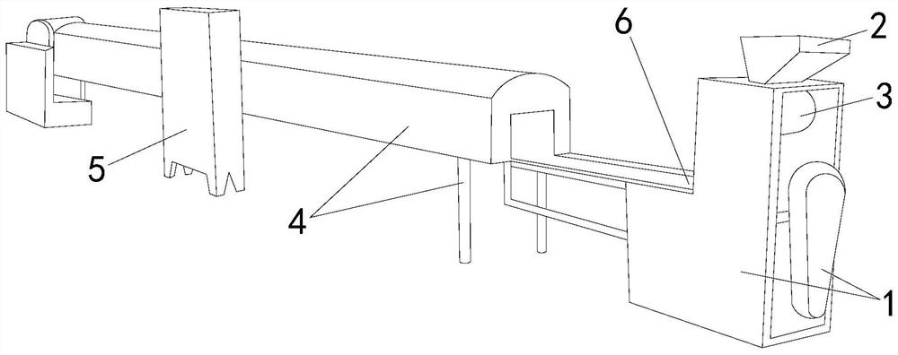
[0023] see figure 1 , the present invention provides a kind of feed assembly line, and its structure comprises: dispersion box 1, feed hopper 2, driving machine 3, conveying frame 4, controller 5, track alignment mechanism 6, described dispersion box 1 top connects feed The bucket 2 is provided with a driving machine 3 between the two to connect with it, and one end of the conveying frame 4 is connected to the dispersion box 1 and is provided with a controller 5 on its side, and the two are connected to each other. The track alignment mechanism 6 is located between the dispersion box 1 and the conveying The frame 4 is connected to the position where the two are connected. The dispersion box 1 is used as the main transmission mechanism of the assembly line equipment. The material is put into the dispersion box 1 through the feeding hopper 2 connected to the top to make it a conveying structure with a feeding function. At the same time, relying on the structure itself The drivi...

Embodiment 2

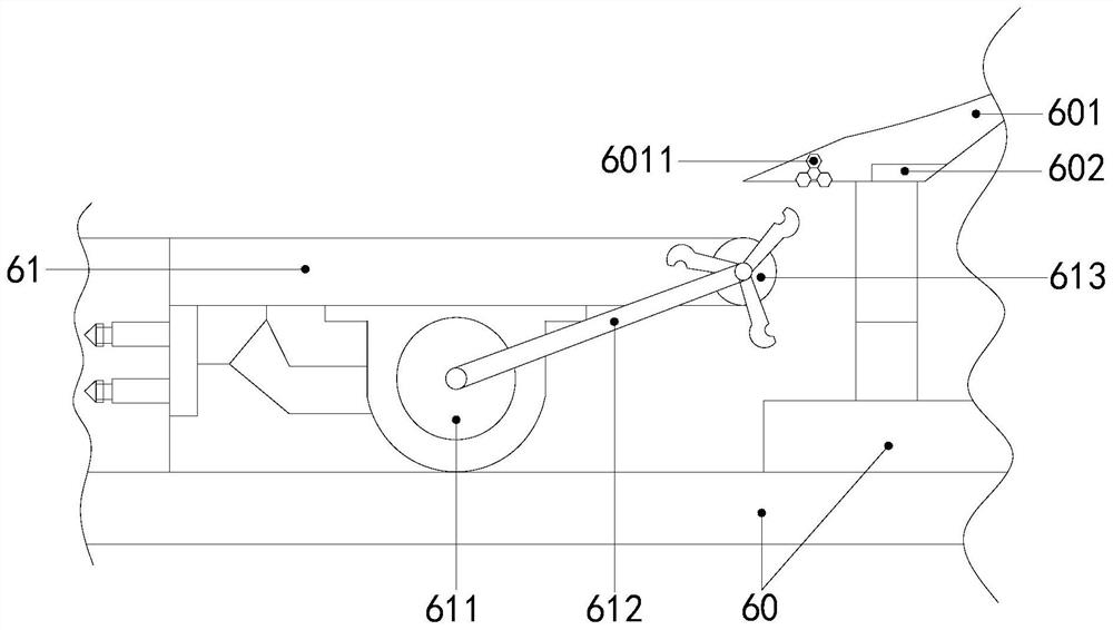
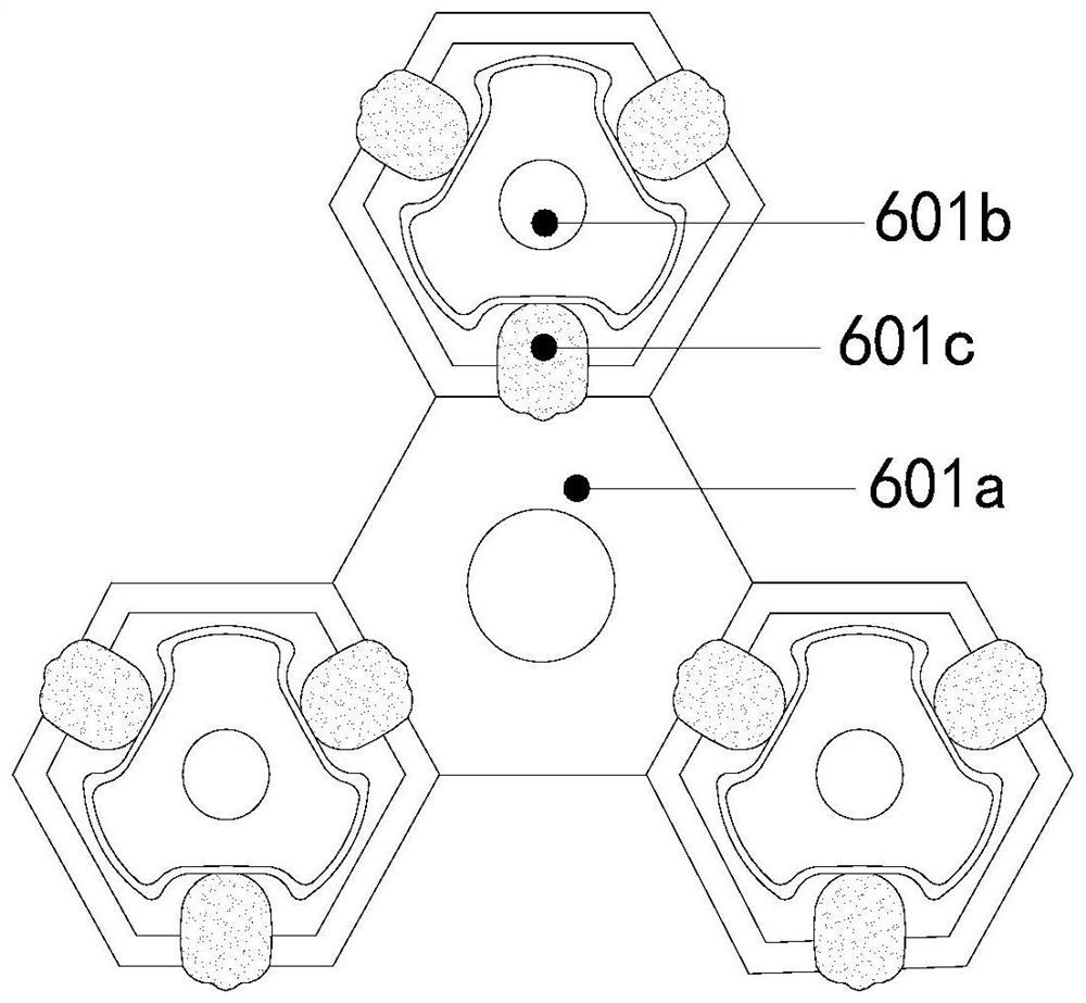
[0029] The description of the second embodiment drawn in conjunction with the first embodiment, combined with figure 2 , image 3 and Figure 5 , the blanking seat 60 and the material receiving plate 61 are set up on one side opposite to each other with a gap left between the two, and the material receiving plate 61 is respectively provided with a driving shaft 611, a transmission belt 612 and a material setting wheel 613. The side of the base point disc wheel 601a is arranged in an equilateral triangle to connect the counterweight disc 601b, and the counterweight disc 601b is equidistantly provided with weak magnetic blocks 601c to connect with it. The two are connected through each other. When the material is put into the hopper 2, the drive shaft 611 provides the source power to start the material wheel 613 through the transmission belt 612. The weak magnetic block 601c will drive the counterweight disc block 601b and The rotation of the base point disc wheel 601a produc...


PUM


Abstract

The invention discloses a feeding assembly line. The feeding assembly line structurally comprises a dispersing box, a feeding hopper, a driving machine, a conveying frame, a controller and a rail alignment mechanism. The top end of the dispersing box is connected with the feeding hopper, the driving machine is arranged between the dispersing box and the feeding hopper and connected with the dispersing box and the feeding hopper. One end of the conveying frame communicates with the dispersing box, and the controller is arranged on the side face of the conveying frame and connected with the conveying frame. The rail alignment mechanism is arranged at the connecting position of the dispersing box and the conveying frame. The feeding assembly line has the beneficial effects that the principlethat magnetic components in the structure attract each other is used for being matched with a special structure that a stepped lower arc curve is matched with an oblique angle, so that materials can better keep a relatively stable sliding speed. A traditional rail clamping plate structure is not adopted, a height fall feeding manner is adopted to avoid rail displacement, and therefore the feedingand conveying speed of materials is increased.

Description

technical field [0001] The invention relates to the field of assembly lines, in particular to a feed assembly line. Background technique [0002] When the parts are interchangeable, there is a concept of tolerance, a qualified part can be installed on all corresponding components arbitrarily, and there is uniformity and repeatability of operation, the assembly line can be formed. The first thing to do in this process is Put the required materials on the workbench of each station. The modern factory adopts a modern production mode to increase the output of the assembly line. The structure between the feed line and the conveying track determines the efficiency of the feed to a certain extent. Some feed lines require Disperse the materials in advance, but the track splint in the vibration rising part of the equipment structure is too small. After the vibration is completed and the material is lowered, the lower track and the docking track are not in the same line, and the track...

Claims


Application Information

Patent Timeline
Patent Type & Authority Applications(China)
IPC IPC(8): B65G37/00B65G47/22B65G47/74B65G69/04B65G47/34
CPCB65G37/00B65G47/22B65G47/34B65G47/74B65G69/0425
Inventor 刘雪娥
Owner 刘雪娥
Why Eureka
Try Eureka