Motor and method for manufacturing the same

A motor and terminal technology, which is applied to the connection structure between the winding end and the substrate and its manufacturing field, can solve the problems of overheating of the winding end, detachment of the winding end, disconnection, etc., and achieve the effect of beautiful soldering

Active Publication Date: 2008-01-16
SANKYO SEIKI MFG CO LTD
View PDF4 Cites 22 Cited by
  • Summary
  • Abstract
  • Description
  • Claims
  • Application Information

AI Technical Summary

Problems solved by technology

Therefore, there is a problem that the wires of the drive coil are thinned or broken due to overheating of the drive coil.
In addition, if the winding end is overheated because soldering on the power supply board takes a long time, the solder that fixes the winding end to the base side of the terminal will melt, causing the windi...

Method used


Image

  • Motor and method for manufacturing the same
  • Motor and method for manufacturing the same
  • Motor and method for manufacturing the same

Examples


Embodiment approach 1

[0038] (The overall structure of the pump unit)

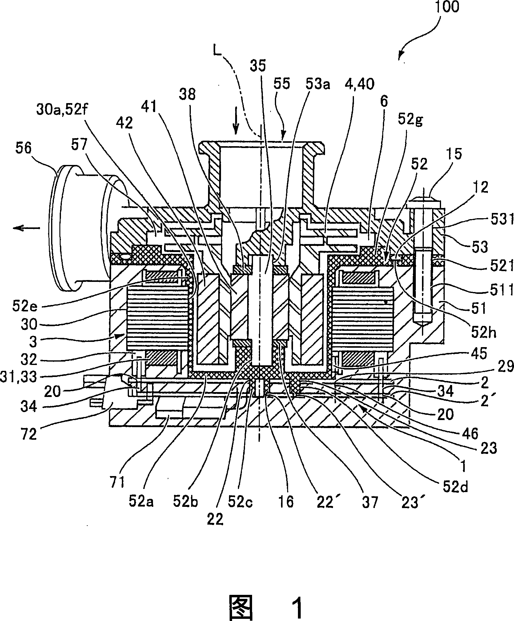
[0039] Fig. 1 is a cross-sectional view of a pump device equipped with a motor applicable to the present invention. The pump device of the present embodiment is a type of pump device generally called a hermetic pump, and incorporates a brushless motor (hereinafter referred to as a motor) with a built-in substrate for power supply described below.

[0040] As shown in FIG. 1 , the pump device 100 equipped with the motor 1 according to the present embodiment has a cup-shaped resin molded body 51 formed by molding the stator portion 3 described below together with the partition wall 52 and a mold covering the partition wall 52 . An upper case 53 with an upper opening is formed. Holes 511, 521, 531 are respectively formed on the resin molded body 51, the partition wall 52, and the upper casing 53, and the common bolts 15 are fastened by using these holes 511, 521, 531, so that the resin molded body 51, the partition wall 52, and t...

Embodiment approach 2

[0087] 5(A) to (D) are explanatory diagrams showing a connection process of connecting the winding end to the flange of the power supply substrate with solder in the motor according to Embodiment 2 of the present invention. In addition, since the basic structure of this embodiment is the same as that of Embodiment 1, the same code|symbol is attached|subjected and shown to a common part, and description is abbreviate|omitted.

[0088] In Embodiment 1, the through portion 20 for drawing out the terminal on the substrate 2 for power supply through which the terminal 34 passes is formed in a groove shape, but in this embodiment, as shown in FIG. 5(A), the through portion for drawing out the terminal is 20 is formed in a circular hole shape. The inner diameter of the terminal lead-out penetration portion 20 having this structure is also set to be much larger than the outer diameter of the terminal 34 . Here, the flange portion 28 is formed along the edge of the terminal lead-out p...


PUM


Abstract

The invention provides a motor and manufacturing method of the motor which can make the coil not generate overheating and perform electric connection of winding end part and flange of baseplate using welding. Firstly, the winding end parts (39a,39b) of a drive coil wind up the base side of binding post (34) formed on the coil bobbin (32). Secondly, the binding post (34) projects up from a slot shape penetrated part (20) for leading out the binding post formed on a baseplate for power supplying and the winding end parts (39a,39b) are lifted, then the ends (39a',39b') of the winding end parts (39a,39b) are connected with the flange (28) of baseplate (2) for power supplying using welding. The flange (28) locally surrounds the circumference of the binding post (34).

Description

technical field [0001] The present invention relates to a motor and its manufacturing method, and more particularly to a connection structure between a winding end and a substrate constituting a drive coil of the motor and its manufacturing method. Background technique [0002] In order to manufacture a motor, as a method of connecting the end of the drive coil wound on the coil bobbin to the power supply substrate, it has conventionally been used to wind the end of the winding on a terminal provided on the coil bobbin and then solder it. Thereafter, the stud is inserted into a through hole formed on the power supply substrate, and the stud is soldered to a flange portion formed on the power supply substrate (for example, refer to Patent Document 1). [0003] As a specific connection method between the terminal and the winding end, a method of winding the winding end around the base side of the terminal, winding the winding end also around the front end of the terminal, and ...

Claims


Application Information

Patent Timeline
IPC IPC(8): H02K3/50
Inventor 藤岛真
Owner SANKYO SEIKI MFG CO LTD
Why Eureka
Try Eureka