FM decoding chip, stereo decoding system and method

A decoding system and stereo technology, applied in the field of stereo decoding systems, can solve the problems of the left channel signal and the right channel signal cannot be clearly separated, the stereo signal and the synchronization signal are large, etc., so as to reduce the phase drift and increase the degree of separation. Effect

Inactive Publication Date: 2008-01-16
MEDIATEK INC
View PDF0 Cites 5 Cited by
  • Summary
  • Abstract
  • Description
  • Claims
  • Application Information

AI Technical Summary

Problems solved by technology

If the delay between the stereo signal and the sync signal is too large, the left and right channel signals cannot be clearly separated

Method used


Image

  • FM decoding chip, stereo decoding system and method
  • FM decoding chip, stereo decoding system and method
  • FM decoding chip, stereo decoding system and method

Examples


Embodiment Construction

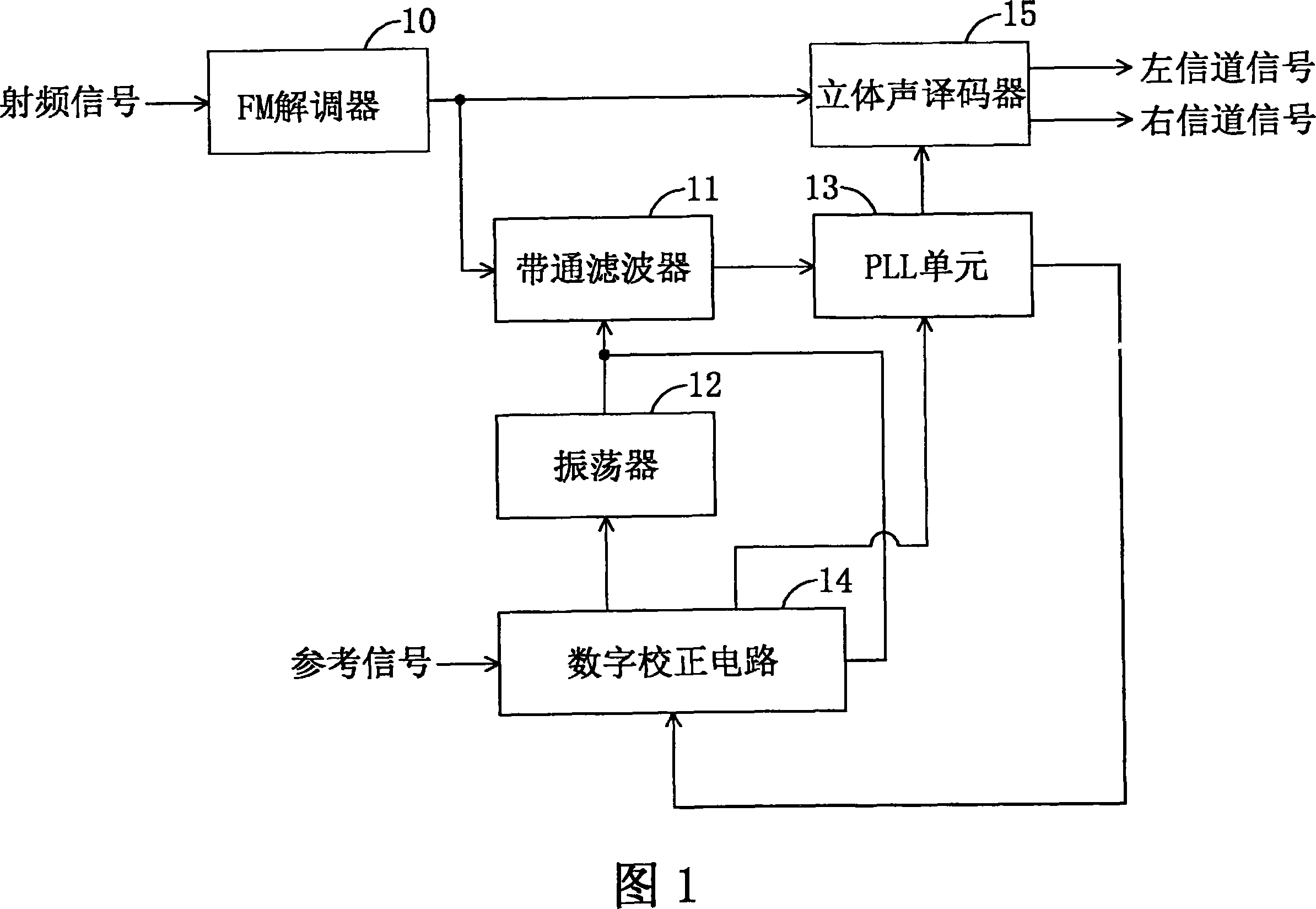
[0017] Fig. 1 is a block diagram of a stereo decoding system according to an embodiment of the present invention. The FM demodulator 10 receives and demodulates a radio frequency signal to generate a stereo multiplexed signal, where the stereo multiplexed signal includes a pilot signal, a left channel signal, and a right channel signal. The band-pass filter 11 has a center frequency fc and a bandwidth between the frequencies fa and fb, where fa is the low-frequency cut-off frequency of the band-pass filter 11 and fb is the high-frequency cut-off frequency of the band-pass filter 11. The oscillator 12 generates and transmits the first signal with the frequency fx to the band-pass filter 11 to filter the pilot signal from the stereo multiplexed signal, where the frequency fx is located between the frequencies fa and fb. The oscillator 12 also transmits the first signal to the digital correction circuit 14 to correct the frequency fx of the first signal to the center frequency fc. Pl...


PUM


Abstract

A stereo decoding system comprises an oscillator, a bandpass filter, a PLL unit and a stereo decoder. The oscillator generates a first signal with a center frequency. The bandpass filter receives a stereo multiplexed signal and the first signal to filter out a pilot signal. The PLL unit receives the pilot signal to generate a PLL output signal. The stereo decoder receives the stereo multiplexed signal and the PLL output signal to separate a left channel signal and a right channel signal from the stereo multiplexed signal.

Description

Technical field [0001] The present invention relates to a stereo decoding system, in particular to a stereo decoding system and method which can reduce phase drift during signal transmission, and its frequency modulation decoding chip. Background technique [0002] Due to the characteristics of frequency modulation (FM) signals, such as better suppression than amplitude modulation (amplitude modulation) signals and the ability to transmit longer distances, one advantage of FM signals is that the signals can be transmitted in stereo. When a stereo decoding system receives and decodes a stereo signal, a synchronization signal is needed to separate the left channel signal and the right channel signal from the stereo signal. The degree of separation between the left channel signal and the right channel signal is determined by the delay between the stereo signal and the synchronization signal, such as phase delay or frequency delay. If the delay between the stereo signal and the sync ...

Claims


Application Information

Patent Timeline
Patent Type & Authority Applications(China)
IPC IPC(8): H04L27/14H04H5/00
CPCH04B1/1653H04H40/63
Inventor 张湘辉黄志坚陈界弘
Owner MEDIATEK INC
Why Eureka
Try Eureka