Metal structural buoyancy pontoon type inner floating tray for storage tank

A metal structure, buoy-type technology, used in containers, packaging, transportation and packaging, etc., can solve the problems of heavy weight, difficult replacement, and large friction coefficient of the floating plate.

Inactive Publication Date: 2008-01-30
张凤球
View PDF2 Cites 2 Cited by
  • Summary
  • Abstract
  • Description
  • Claims
  • Application Information

AI Technical Summary

Problems solved by technology

Disadvantages of traditional steel floating discs: 1. This kind of floating disc is welded by steel plates with many welds. Due to the inevitable defects of welds, it is easy to cause partial leakage of the floating disc, which may lead to sinking; 2. The lifting of the floating plate in the storage tank is guided by the column. If the center of gravity of the floating plate is slightly shifted, it will cause chucking and sinking of the plate; Large, the sealing rubber belt is prone to damage, difficult to replace, and inconvenient to maintain; 4. The floating plate is heavy, consumes a lot of metal materials, and the cost is high; 5. The manufacturing and installation of the floating plate are all on-site construction, and the cycle is long
In the inner floating disc of the traditional aluminum buoy, there is an oil and gas space with a height of about 200mm under the cover plate of the floating disc, so the sealing performance is poor.
[0003] Existing aluminum floating discs, such as my country's patent ZL99257763.2 "Assembled floating discs for storage tanks", the floating disc is to fix the buoy on the beam, and the beam is supplemented by a cover plate. The disadvantage is: more materials are used

Method used


Image

  • Metal structural buoyancy pontoon type inner floating tray for storage tank
  • Metal structural buoyancy pontoon type inner floating tray for storage tank

Examples


Embodiment Construction

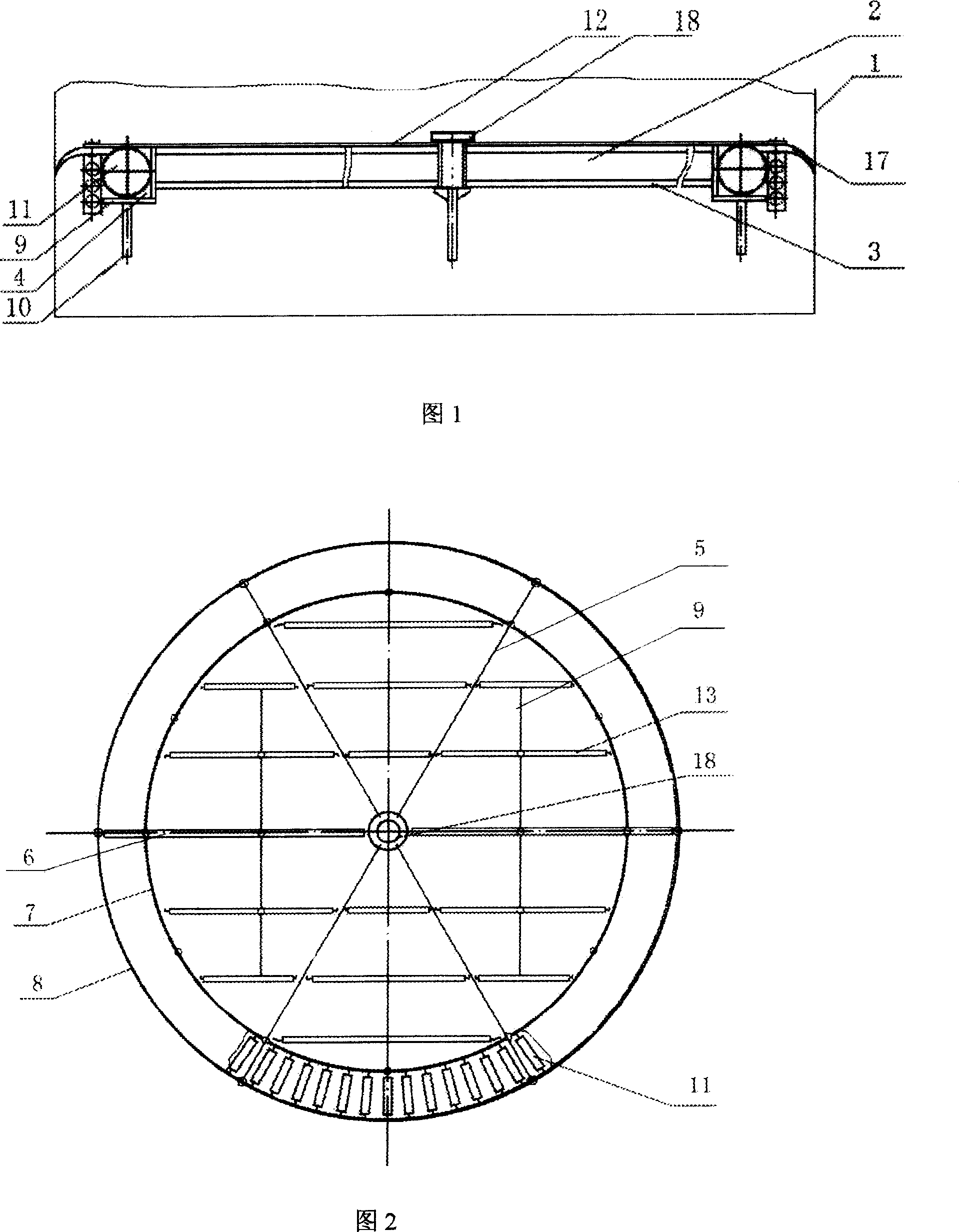
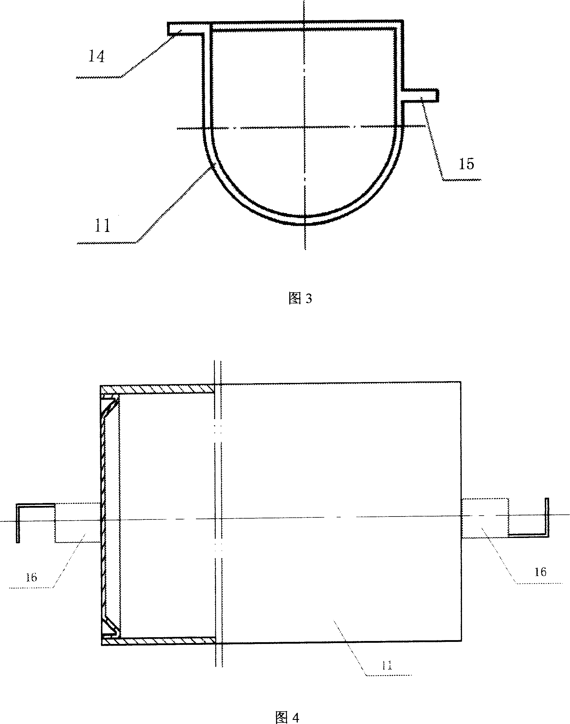
[0009] The present invention will be further described below in conjunction with the accompanying drawings and embodiments.

[0010] The floating disc 2 is installed in the storage tank shell 1. It can be seen from Figure 1 that it consists of a radioactive metal framework and a buoy in the metal framework. The floating plate 2 is installed in the storage tank shell 1 filled with medium, floats above the liquid surface, and floats up and down with the liquid surface. . The floating disc 2 is composed of two parts, the middle part of the floating disc is the middle floating disc 3 , and the peripheral part of the floating disc is the peripheral cabin 4 . The middle floating plate (3) is made up of U-shaped buoys (13), and is fixed on the inner ring beam 7, and the inner ring beam 7 of the surrounding cabin 4 is formed by connecting the ribs 9 and the cylindrical buoys 11. Various accessories are installed on the floating plate 2, such as sealing device, static electricity der...


PUM


Abstract

The invention discloses a metal structure displacer-typed internal floating disc for a storage tank. The invention consists of a radioactivity metal framework and a camel arranged in the metal framework; the floating disc (2) is arranged in a shell (1) of the storage tank and consists of a middle floating disc (3) and a peripheral cabin (4); the middle floating disc (3) consists of 6 main beams and a U-shaped floating disc (13); one end of the middle floating disc (3) is fixed to a central plate (18) while the other end of the middle floating disc (3) is fixed to an external ring beam (8) by an internal ring beam (7); a stiffener (9) is arranged between the internal ring beam (7) and the external ring beam (8); a supporting leg (10) is fixed to the stiffener (9); one end of a cylindrical floating disc (11) is fixed to the peripheral cabin (4) consisting of the external ring beam (8) and the middle of the internal ring beam (7). The invention has the advantages that the beam and the camel is injected into a whole as the U-shaped camel is arranged in the middle of the floating disc, the material is saved; the oil gas space is small, and the sealing performance is improved; the upper part of the floating disc is a rectangle; the strength of the floating disc is improved and the stability is good.

Description

technical field [0001] The technical solution of the present invention belongs to the technical field of large containers, specifically, it belongs to the field of large containers with floating lids, and belongs to the field of B65D 88 / 34 according to the International Patent Classification. Background technique [0002] In order to reduce the evaporation loss of the medium in the storage tank and the pollution of the medium to the air, a floating plate is usually installed in the storage tank. Disadvantages of traditional steel floating discs: 1. This kind of floating disc is welded by steel plates with many welds. Due to the inevitable defects of welds, it is easy to cause partial leakage of the floating disc, which may lead to sinking; 2. The lifting of the floating plate in the storage tank is guided by the column. If the center of gravity of the floating plate is slightly shifted, it will cause chucking and sinking of the plate; Large, the sealing rubber belt is prone...

Claims


Application Information

Patent Timeline
IPC IPC(8): B65D88/34B65D90/00
Inventor 张凤球赵勇赵薇程菲
Owner 张凤球
Why Eureka
Try Eureka