
System and control method of oil burner's suitable burning ratio using air pressure sensor

A technology of air pressure and air-fuel ratio, applied in the combustion method, control combustion, burner and other directions, can solve the problems of changing the blower, changing the resistance of the blower, and unstable combustion of the oil furnace

Inactive Publication Date: 2008-01-30
KYUNGDONG NETWORK
View PDF0 Cites 6 Cited by
  • Summary
  • Abstract
  • Description
  • Claims
  • Application Information

AI Technical Summary

Problems solved by technology

[0009] First of all, after installing the oil furnace, when the oil furnace is turned on or off, due to the soot generated, the internal flow resistance of the heat exchanger may change
[0010] Second, if the damper is adjusted during production, the resistance of the blower may change according to the length of the exhaust cylinder
[0011] Third, even with the same exhaust stack, the resistance of the blower may change frequently due to the wind
[0012] Therefore, the amount of air supplied to the oil burner often deviates from the optimum amount of air required for combustion of the burner, causing the burner to become unstable

Method used


Image

  • System and control method of oil burner's suitable burning ratio using air pressure sensor
  • System and control method of oil burner's suitable burning ratio using air pressure sensor

Examples


Embodiment Construction

[0026] Reference will now be made in detail to preferred embodiments of the present invention.

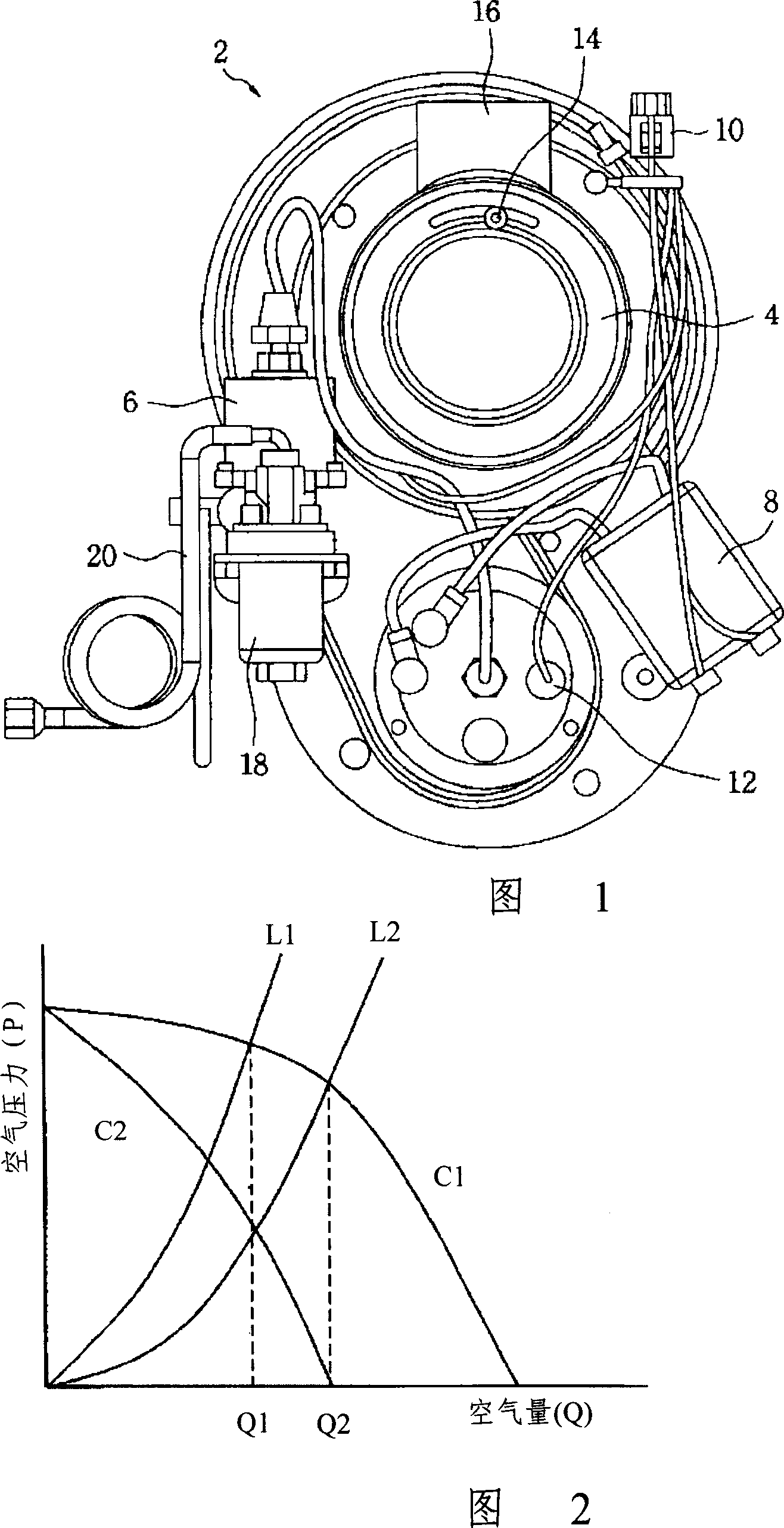
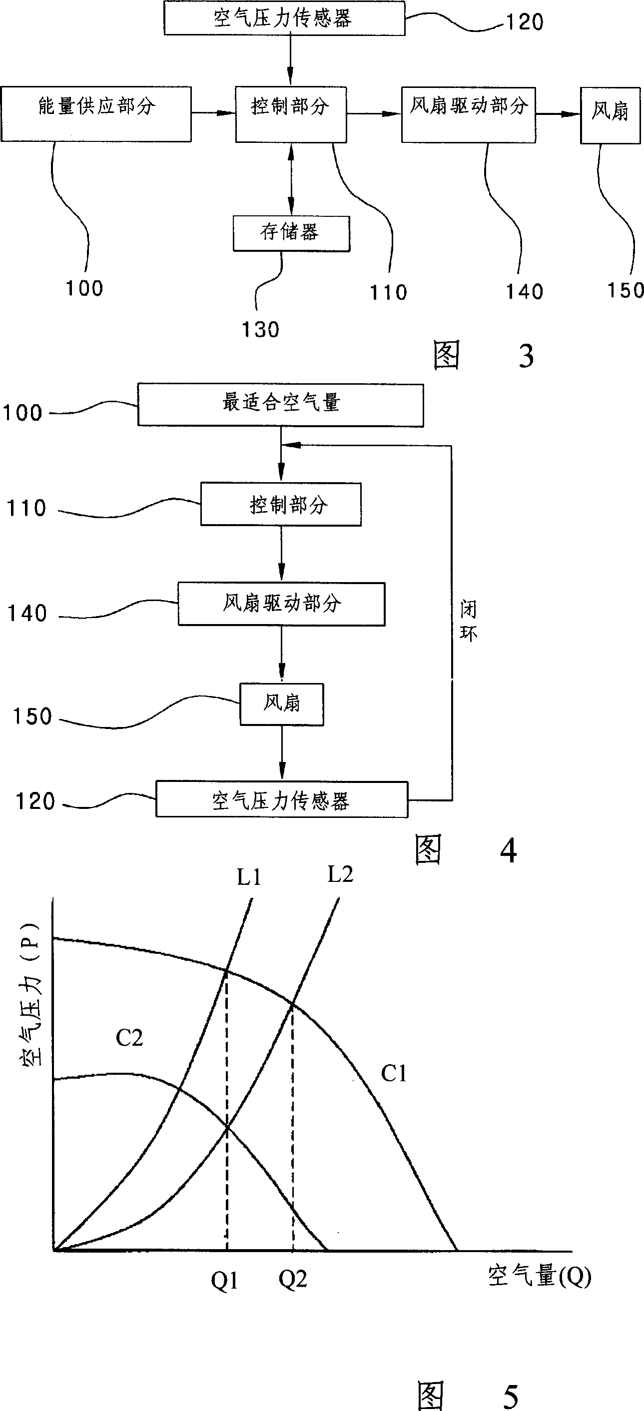
[0027] 3 is a block diagram illustrating a system structure for controlling the air-fuel ratio by an air pressure sensor in the present invention, FIG. 4 is a diagram illustrating a program for controlling the air-fuel ratio of an oil burner in the present invention, and FIG. Diagram for the method of adjusting the air volume by changing the RPM of the fan installed inside the oil furnace.

[0028] Referring to Fig. 3, the system among the present invention comprises energy supply part 100, and this energy supply part 100 is used for receiving electrical energy, converts electrical energy into predetermined driving voltage, and driving voltage is provided to the system; Fan 150, is used for from The energy supply part 100 receives the basic driving energy, then supplies the required air for the combustion of the oil burner; the fan drive part 140 is used to drive the fan 150 as a c...


PUM


Abstract

Disclosed are a system and a method for precisely controlling an air fuel ratio of an oil burner, which is extensively used in a household boiler, an industrial boiler, or a heater, using an air pressure sensor. The system includes a power supplying part, a fan for supplying air required for combustion of the oil burner by receiving driving voltage from the power supplying part, a fan driving part serving as a controller which drives the fan, an air pressure sensor, which is installed at a side of a flow path of air supplied from the fan so as to detect an amount of the supplied air, and a contro 1 part for outputting an optimum RPM of the fan to the fan driving part by comparing a signal detected by the air pressure sensor with preset data related to an optimum amount of air. The method includes the steps of detecting an amount of air being supplied through a fan using the air pressure sensor, calculating an optimum RPM of the fan using a controller by comparing a signal about the amount of the air with preset data related to an optimum amount of air, outputting the RPM calculated by means of the controller to a fan driving part, and rotating the fan according to the calculated RPM input into the fan driving part.

Description

technical field [0001] The present invention relates to a system and method for controlling the air-fuel ratio of an oil-fired furnace, and more particularly, to a system and method for accurately controlling the air-fuel ratio of an oil-fired furnace using an air pressure sensor, which is widely used in household boilers , Industrial boilers and heaters. Background technique [0002] Generally, boilers used for room or hall heating are divided into oil-fired boilers, gas-fired boilers and electric boilers according to the type of fuel supplied to the boiler. Corresponding to the size of the room or hall or the purpose of their installation, boilers are developed and used differently. Oil-fired boilers among these boilers, as well as heaters that use oil as fuel, include oil-fired burners. [0003] In particular, precise control of the air-fuel ratio is very important for oil burners. Recently, the control of the air-fuel ratio in oil-fired furnaces has become the most im...

Claims


Application Information

Patent Timeline
Patent Type & Authority Applications(China)
IPC IPC(8): F23N3/02
CPCF23D11/001F23N2039/06F23N3/082F23N2023/36F23N2023/44F23N2025/06F23N2033/08F23N3/02F23N2223/36F23N2223/44F23N2225/06F23N2233/08F23N2239/06F24H9/20
Inventor 闵泰植
Owner KYUNGDONG NETWORK
Learn More