Liftable storage device

A storage device, lift-type technology, applied in the field of lift-type storage devices, can solve the problems that it is not easy to take out, things that fall in the cabinet 1 cannot be seen, difficult to operate, etc., so as to achieve easy access to things and increase the size of the storage space. Lower stroke, ease of use

Inactive Publication Date: 2011-02-09
PANASONIC CORP
View PDF5 Cites 1 Cited by
  • Summary
  • Abstract
  • Description
  • Claims
  • Application Information

AI Technical Summary

Problems solved by technology

Therefore, the storage rack 2 cannot be lowered very low. For users with short stature, a step is needed to access things, and the operation is more difficult.
In addition, when the storage rack is lowered to the lowest position, the lower 1 / 3 of the storage cabinet 1 is blocked by the storage rack 2, even if there is something falling in the storage cabinet 1, it cannot be seen, and it is not easy to take it out.

Method used


Image

  • Liftable storage device
  • Liftable storage device
  • Liftable storage device

Examples


Embodiment 1

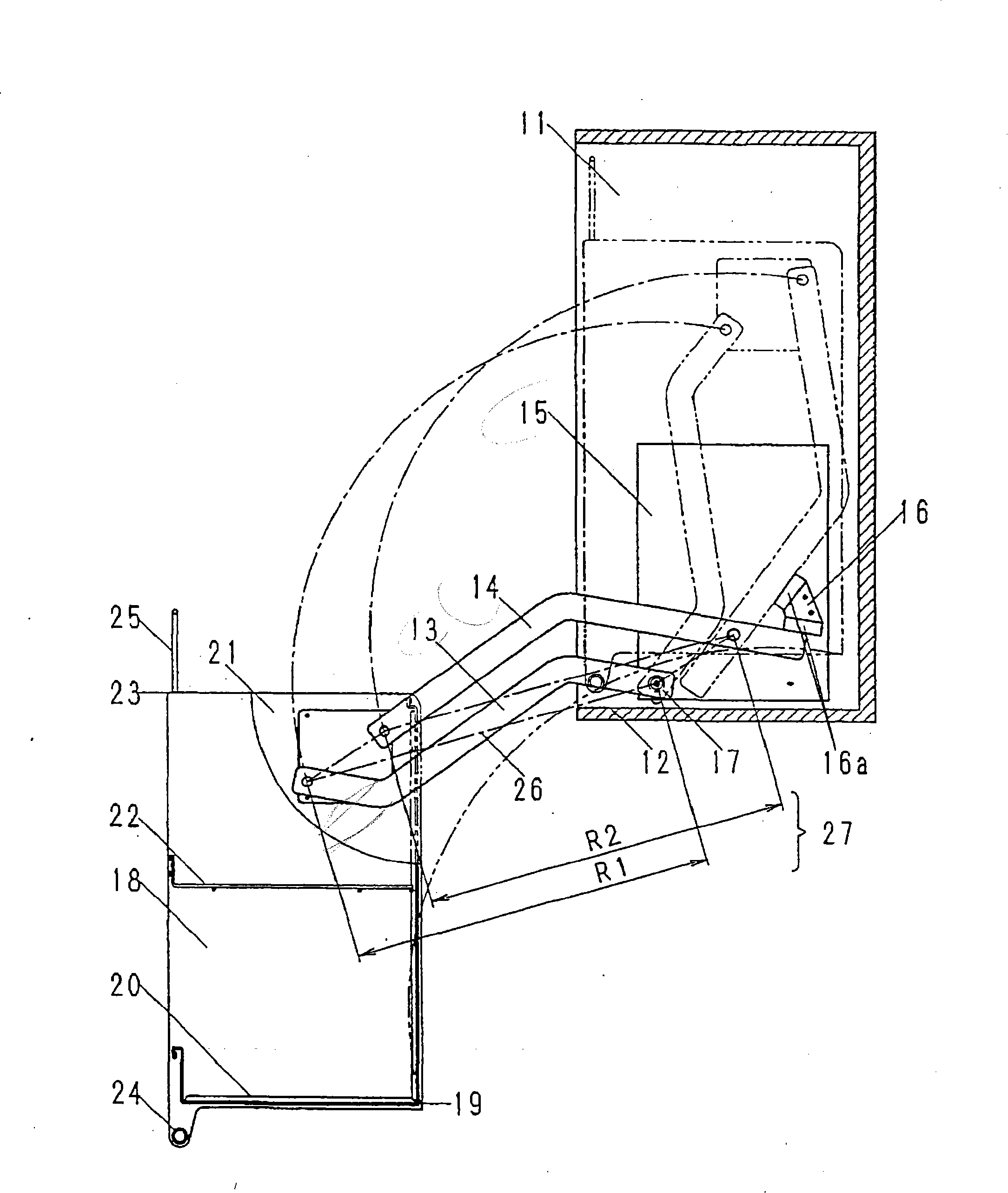
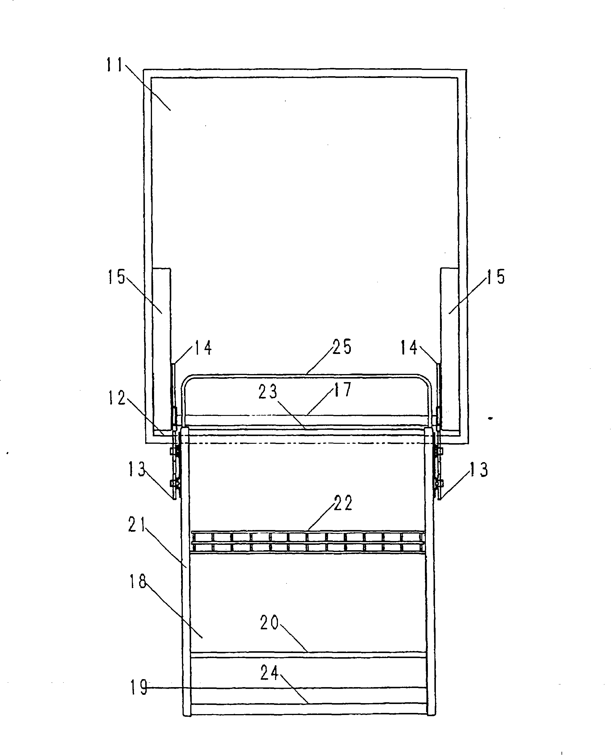
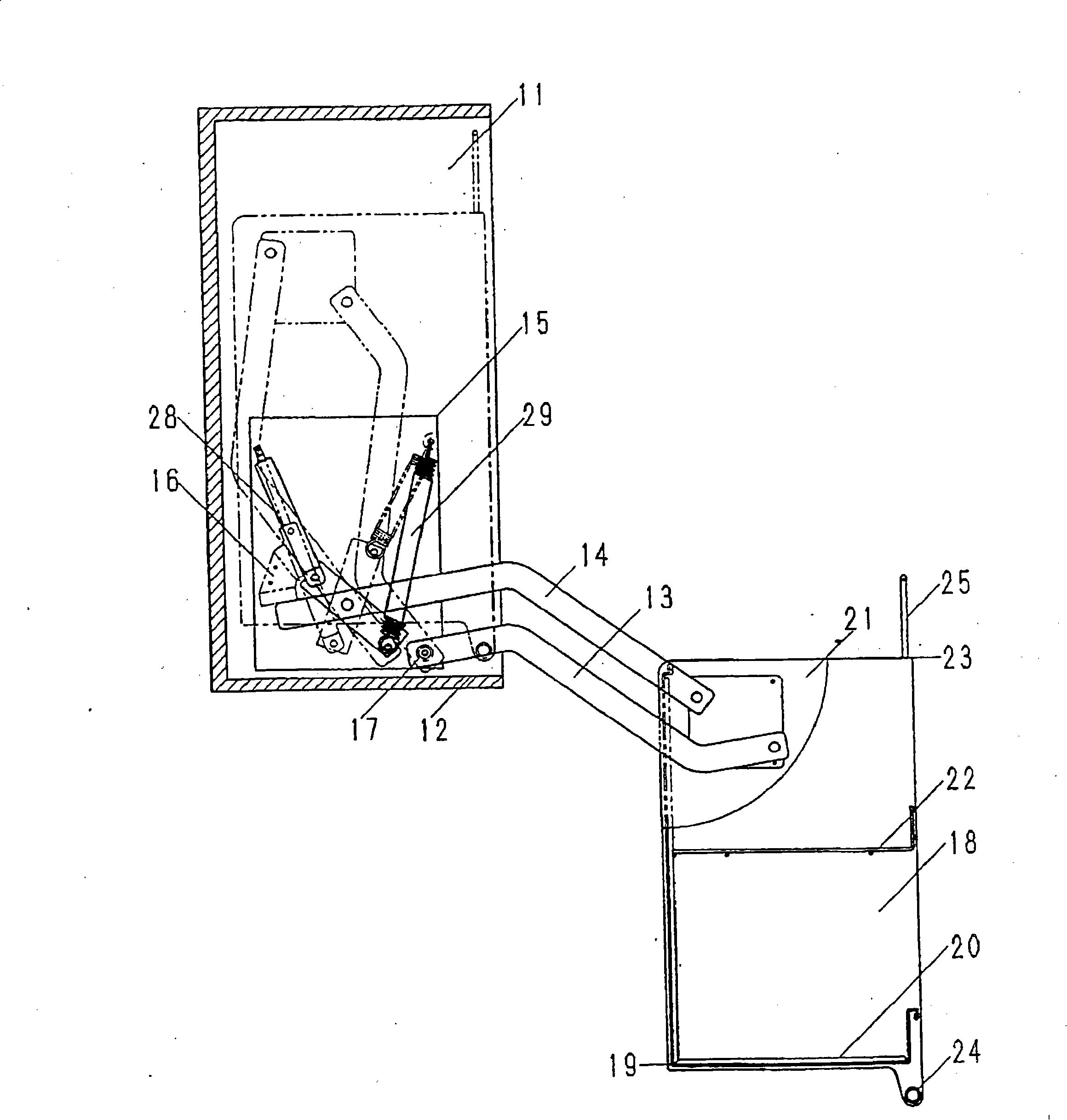
[0033] Such as Figure 1 ~ Figure 4 As shown, the storage cabinet 11 is arranged above the wall surface of a kitchen or the like. On the two side surfaces inside the storage cabinet 11, on the same plane, two flat-plate-shaped first rotating arms 13 and second rotating arms 14 are arranged front and rear. In order to avoid colliding with the bottom plate 12 of the storage cabinet, the first rotating arm 13 is slightly bent first, and then the front part is bent in the opposite direction to form a substantially S-shaped shape. Touch, roughly into an L-shape. An elevating support device 15 capable of rotating and supporting the first rotating arm 13 and the second rotating arm 14 is also provided. Moreover, by making the 1st rotating arm 13 substantially S-shape, it can avoid colliding with the front part of the 2nd rotating arm 14. As shown in FIG.

[0034] Stopper 16 is arranged on the outside of lifting support device 15, and the limiter of rubber cushioning material 16a i...

Embodiment 2

[0055] Figure 5 It is a lift-type storage device according to Embodiment 2 of the present invention, showing a left side cross-sectional view of a storage rack in a lowered state.

[0056] The difference from Embodiment 1 is that the rotating arm is made of two substantially L-shaped arms 33 and 34. In addition, the same configuration as the above-mentioned embodiment is marked with the same serial number, and the description thereof will be omitted.

[0057] Its action and function are explained below. The rotating arm is made into two substantially L-shaped arms 33, 34, and after the curved shape becomes smaller, the discharge condition of the two rotating arms 33, 34 is good during stamping, and the cost of the two rotating arms 33, 34 can be reduced.

Embodiment 3

[0059] Figure 6 It is the elevating type storage device of the third embodiment of the present invention, showing the left sectional view of the storage rack in the lowered state.

[0060] The point of difference from Embodiments 1 and 2 is that the swivel arm is formed of a substantially L-shaped arm 33 and a linear arm 35 . The same configurations as those of the above-mentioned embodiments are denoted by the same numbers, and descriptions thereof are omitted.

[0061] Its action and function are explained below. After the swivel arm is made substantially into the L-shaped arm 33 and the linear arm 35, the blanking situation of the linear arm 35 is good, so the cost of the linear arm 35 can be reduced.


PUM


Abstract

This invention relates to a storage unit having an elevating rack capable of selectively elevating and descending between a drawn position and a retracted position. The storage unit comprises a storage cabinet 11, a storage rack 18 removably accommodated within the storage cabinet 11, rocking arms 13 and 14 supporting the storage rack 18 relative to the storage cabinet 11 for movement a relatively large angular distance between the drawn position, in which the storage rack 18 is drawn out of the storage cabinet 11, and the retracted position in which the storage rack 18 is completely accommodated within the storage cabinet 11, and a supporting device 15 supporting the rotating arms 13 and 14 rotatable. When in the drawn position, the storage rack 18 has a top portion 23 held at a level equal to or about equal to the level of a bottom plate 12 of the storage cabinet 11 so that an user can make access to the storage rack 18 with no need to stand on tiptoe.

Description

[0001] This application is a divisional application, the application number of its parent application: 00106253.0, the application date: 2000.5.19, the name of the invention: lifting storage device technical field [0002] This invention relates to a lift storage device for use in kitchens and the like. Background technique [0003] Existing elevating storage devices include elevating storage devices described in JP-A-7-303534 and the like. Figure 9 It shows the oblique view of the appearance of the existing lifting storage device, Figure 10 It is a side view of an existing lifting storage device. like Figure 9 , Figure 10 As shown, the existing elevating storage device is composed of a storage cabinet 1, a storage rack 2 arranged on the inside of the storage cabinet 1, and a pair of lifting support devices 5, and the support device has linear rotating arms 3, 4, which can The storage rack 2 can be freely lifted and lowered. [0004] The lifting of the storage rack 2 ...

Claims


Application Information

Patent Timeline
Patent Type & Authority Patents(China)
IPC IPC(8): A47B51/00A47B77/04A47B77/16
Inventor 垰统雄白井滋大山真
Owner PANASONIC CORP
Why Eureka
Try Eureka