Molding method of terminal

A molding method and terminal technology, applied in the manufacture of contacts, etc., can solve problems such as increased production costs, scrapped terminals, unstable terminal dimensions, etc., and achieve the effects of saving production costs and stabilizing the terminal structure

Inactive Publication Date: 2008-02-06
DEYI PRECISION ELECTRONIC IND CO LTD PANYU
View PDF0 Cites 5 Cited by
  • Summary
  • Abstract
  • Description
  • Claims
  • Application Information

AI Technical Summary

Problems solved by technology

The terminal 20 is stamped from a plate-shaped metal material, including a base 21 accommodated in the terminal receiving groove 11 and an elastic arm 22 extending from the base, wherein the base 21 is composed of a connecting body 211 and a vertical body 212 perpendicular to each other; The elastic arm 22 is in compression contact with the chip module 30, and is formed by bending and extending the end of the vertical body 212 through a bending line 221. The bending line 221 forms a certain angle with the circuit board 40, so that the elastic arm of the adjacent terminal 20 can There is a relatively large distance between 22, that is, the elastic arm 22 extends away from the vertical body 212. Although the elastic arm extends away from the vertical body to increase the elasticity of the elastic arm, the elastic arm is bent by a bending line. The terminal is formed by extension, and the terminal is stamped from a metal sheet. During the stamping process, the size of the terminal is often unstable due to the inaccurate alignment of the bending line, and the elastic arm is easily in the bending line during the bending process. Breakage, resulting in a large number of scrapped terminals, will inevitably increase production costs

Method used


Image

  • Molding method of terminal
  • Molding method of terminal
  • Molding method of terminal

Examples


Embodiment Construction

[0024] The present invention will be further described below in conjunction with the accompanying drawings and specific embodiments.

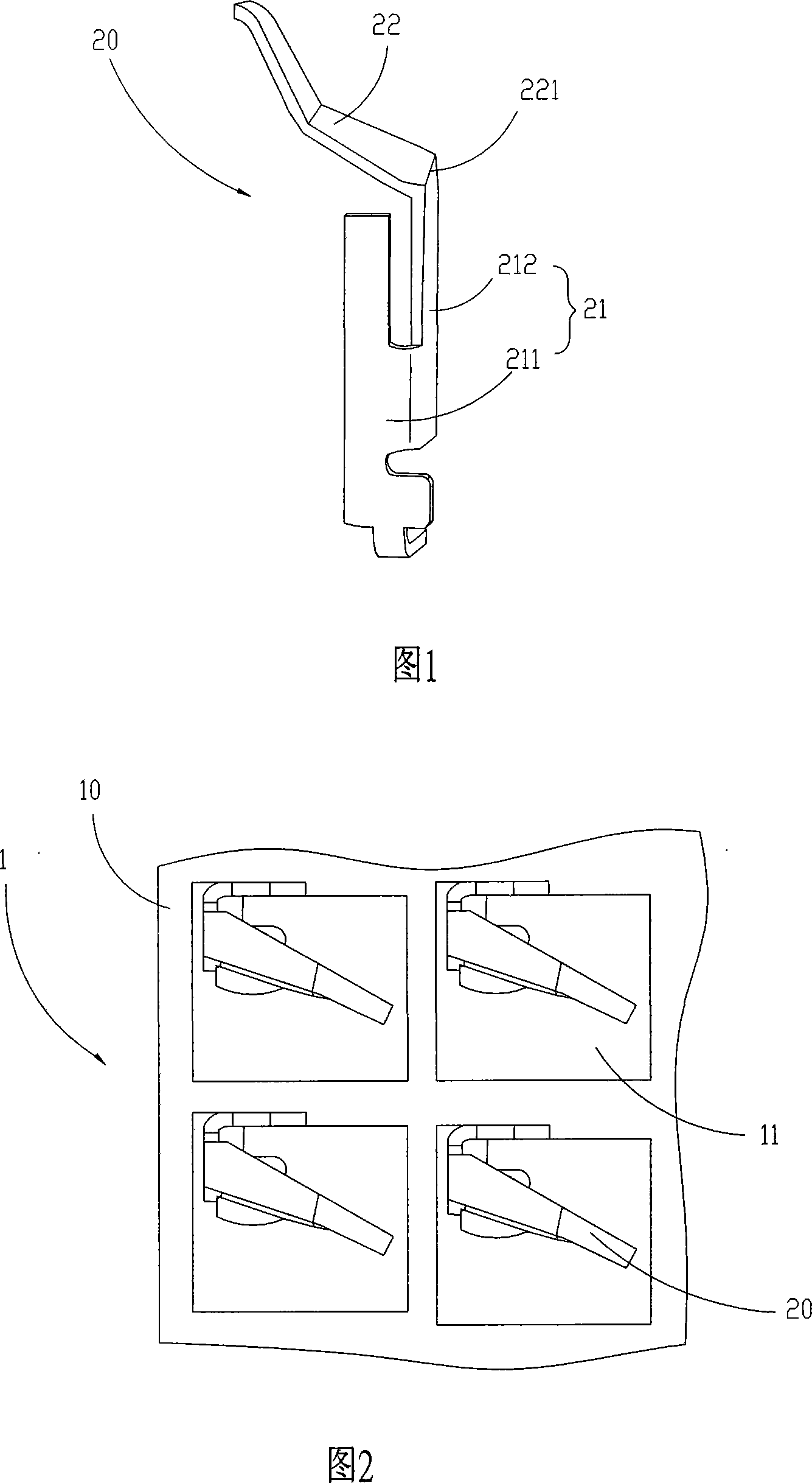
[0025] Please refer to FIG. 3 to FIG. 10 , the forming method of the terminal 10 of the present invention is to twist or rotate the terminal 10 by a certain angle in a certain way, so that the front-to-back distance between adjacent terminals 10 is increased, and the left-to-right distance is reduced, and then the terminal is accommodated. In an insulating body 20, the terminal density effect is achieved, and the process will be discussed in detail below.

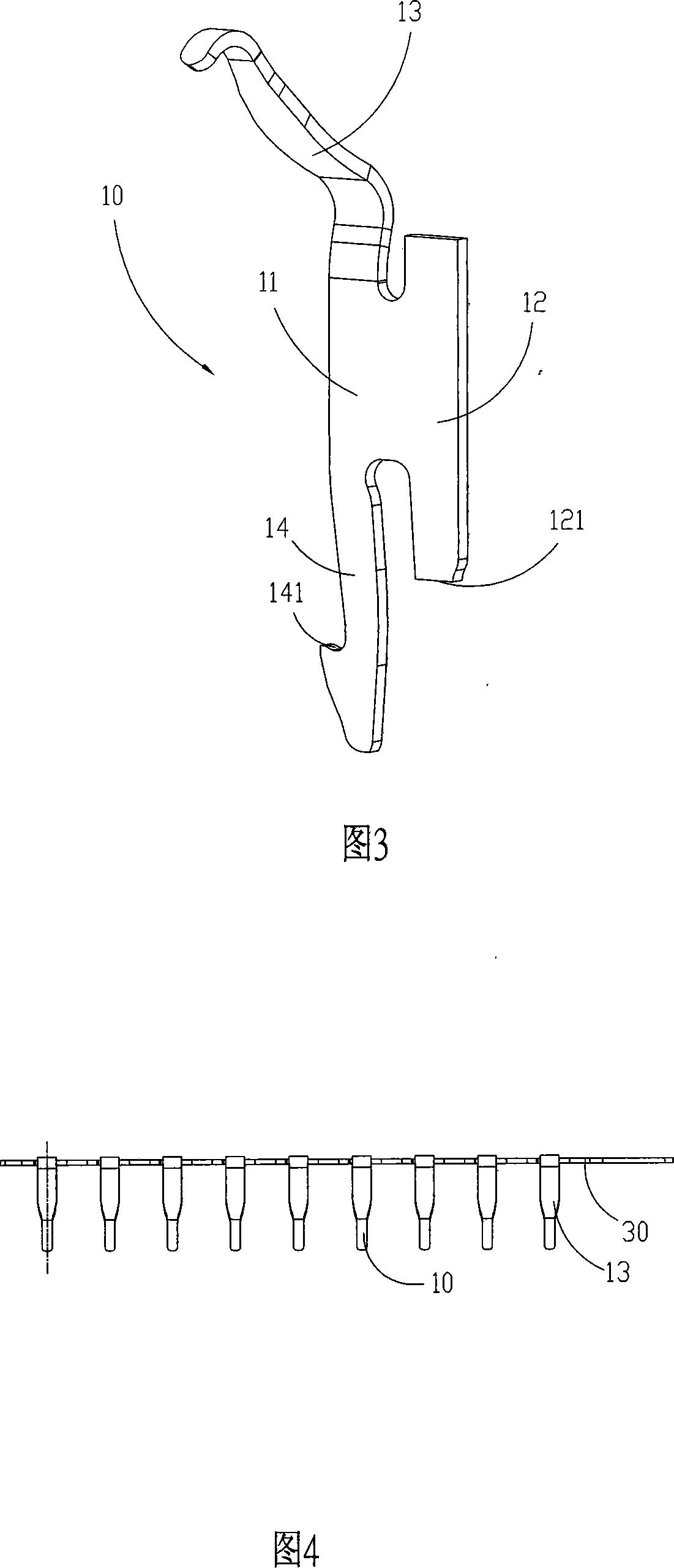
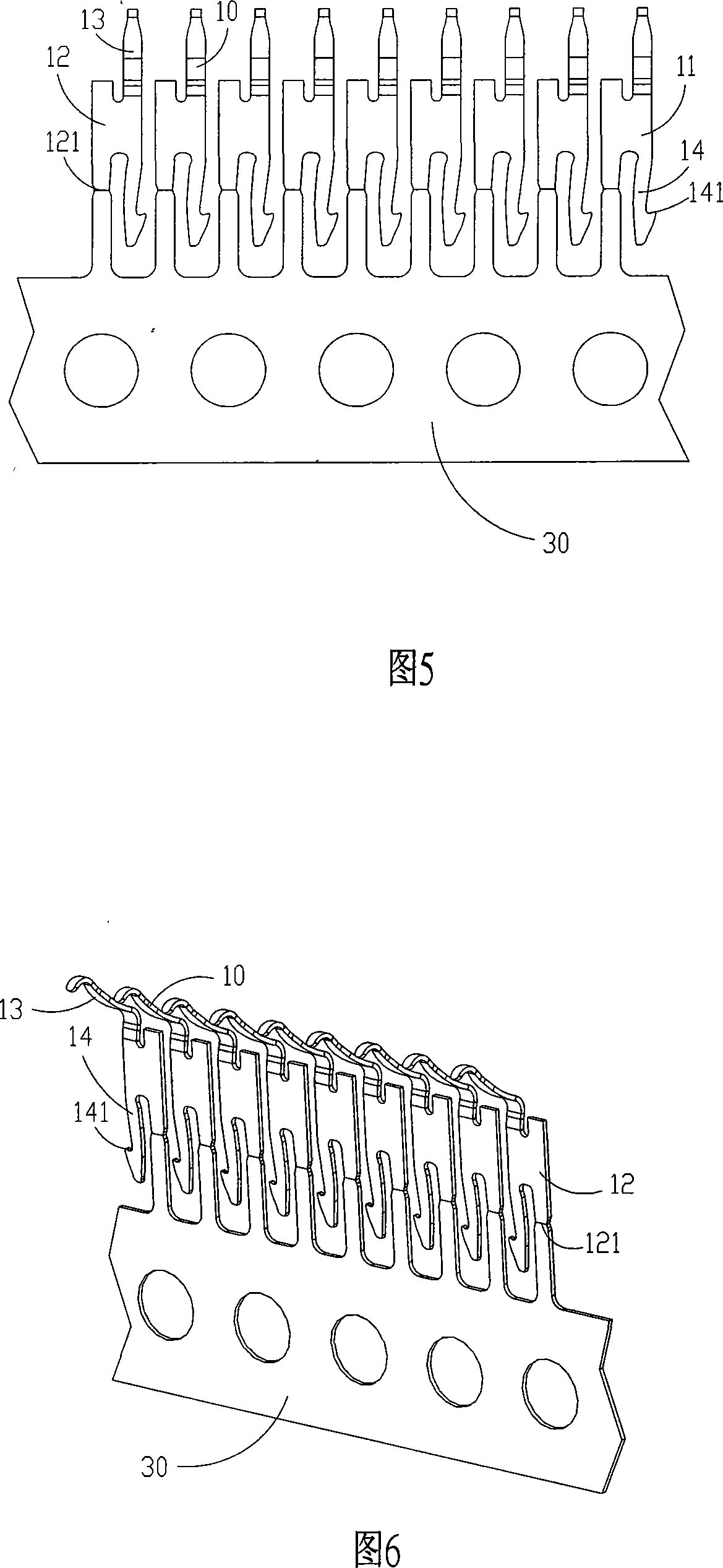
[0026] Please refer to FIG. 3 to FIG. 6, and FIG. 3 to FIG. 6 are schematic diagrams of the structure of the terminal 10 before rotation or twisting. A plurality of terminals 10 are integrally stamped and formed on a terminal strip 30. Each terminal 10 includes a main body 11 and consists of The base portion 12 , the elastic arm 13 and the welding portion 14 extend from the main body portion...


PUM


Abstract

The invention relates to a terminal shaping method, comprising the following steps: (1) a plurality of terminals and a terminal material belt are shape integrally; (2) a first device is provided to fix the terminal material belt; (3) providing a second device which has a plurality of clamping claws clamping on a plurality of terminals on the other end of the terminal material belt; (4) the first device and the second device fix the two opposite ends of the terminals and the terminal material belt, and the terminals are made to return or rotate at a certain angle so as to cut off the terminals and the terminal material belt; (5) the clamping claws clamp the terminals and put the terminals into an insulating body. The present invention fixes the two opposite ends of the terminals and the terminal material belt through the two devices so as to make the terminals return or rotate at a certain angle to increase the longitudinal distance between two adjacent terminals and reduce the horizontal distance so as to reach the terminal intensification effect.

Description

【Technical field】 [0001] The invention relates to a molding method of a terminal, in particular to a molding method of a terminal used to electrically connect a chip module and a circuit board. 【Background technique】 [0002] With the development of the electrical connector industry towards miniaturization, high density and high stability, the requirements for the electrical performance of its terminals are getting higher and higher. The electrical performance of the terminals mainly depends on the contact force between the terminals and the chip module. However, the terminals themselves are very small and must be densely arranged and accommodated in the insulating body. Therefore, there is a large offset between the elastic arm of the existing terminal and the holding part of the terminal, so as to increase the force arm of the terminal and increase the force of the terminal. The elasticity of the elastic arms, but how to make the elastic arms of adjacent terminals have a l...

Claims


Application Information

Patent Timeline
Patent Type & Authority Applications(China)
IPC IPC(8): H01R43/16
Inventor 刘飞
Owner DEYI PRECISION ELECTRONIC IND CO LTD PANYU
Why Eureka
Try Eureka