
Rotary lobe pump

一种凸轮泵、凸轮转子的技术,应用在旋转活塞式泵、泵、旋转活塞式机械等方向,能够解决产品损失、易于出错、消耗时间等问题

Active Publication Date: 2008-02-13
ITT MFG ENTERPRISES LLC
View PDF0 Cites 5 Cited by
  • Summary
  • Abstract
  • Description
  • Claims
  • Application Information

AI Technical Summary

Problems solved by technology

The problem with this type of cleaning and sanitizing process is that it is time consuming and error prone
Any errors in the cleaning process may result in contamination of pumped material and / or loss of product

Method used


Image

  • Rotary lobe pump
  • Rotary lobe pump
  • Rotary lobe pump

Examples


Embodiment Construction

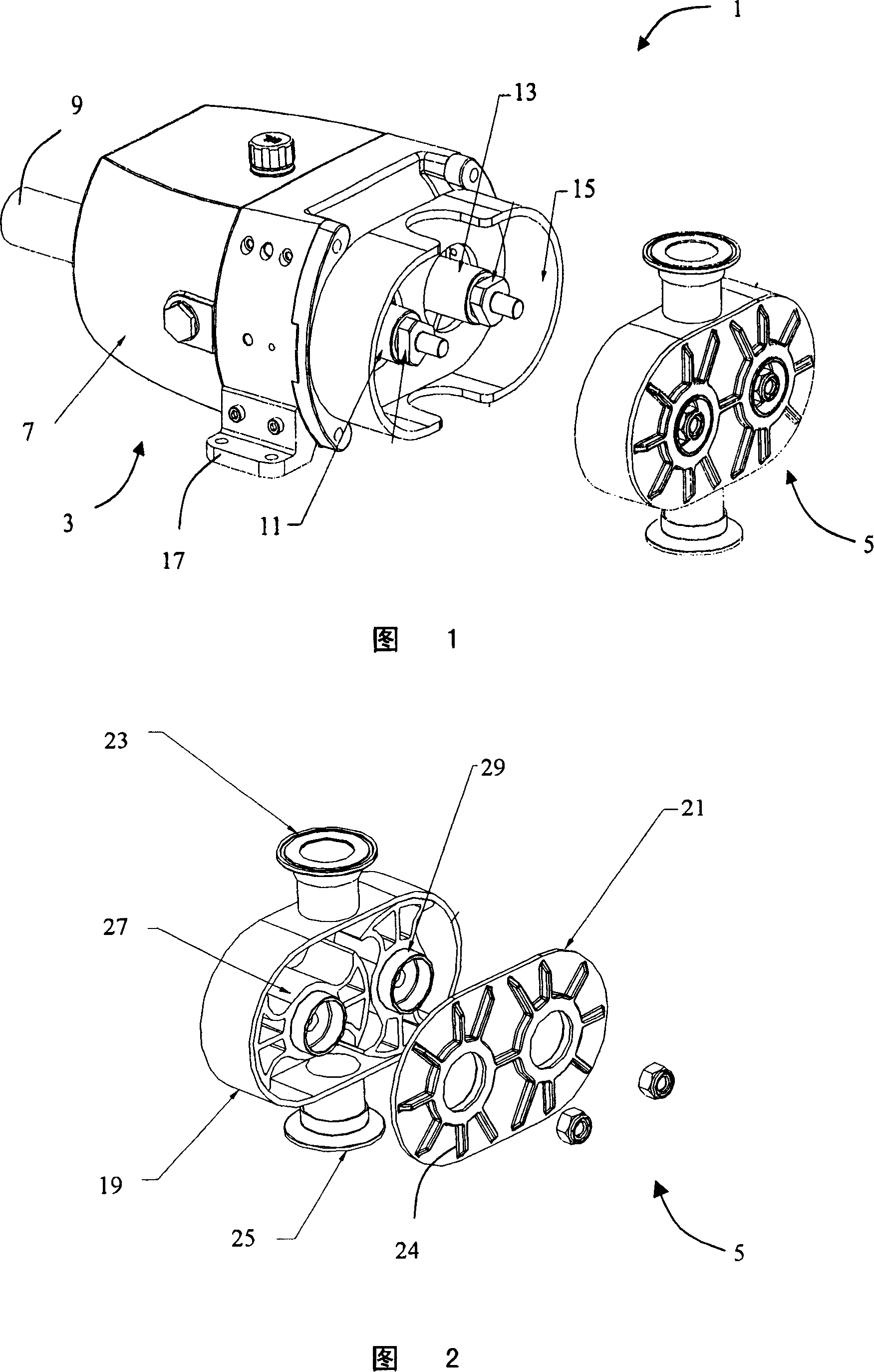
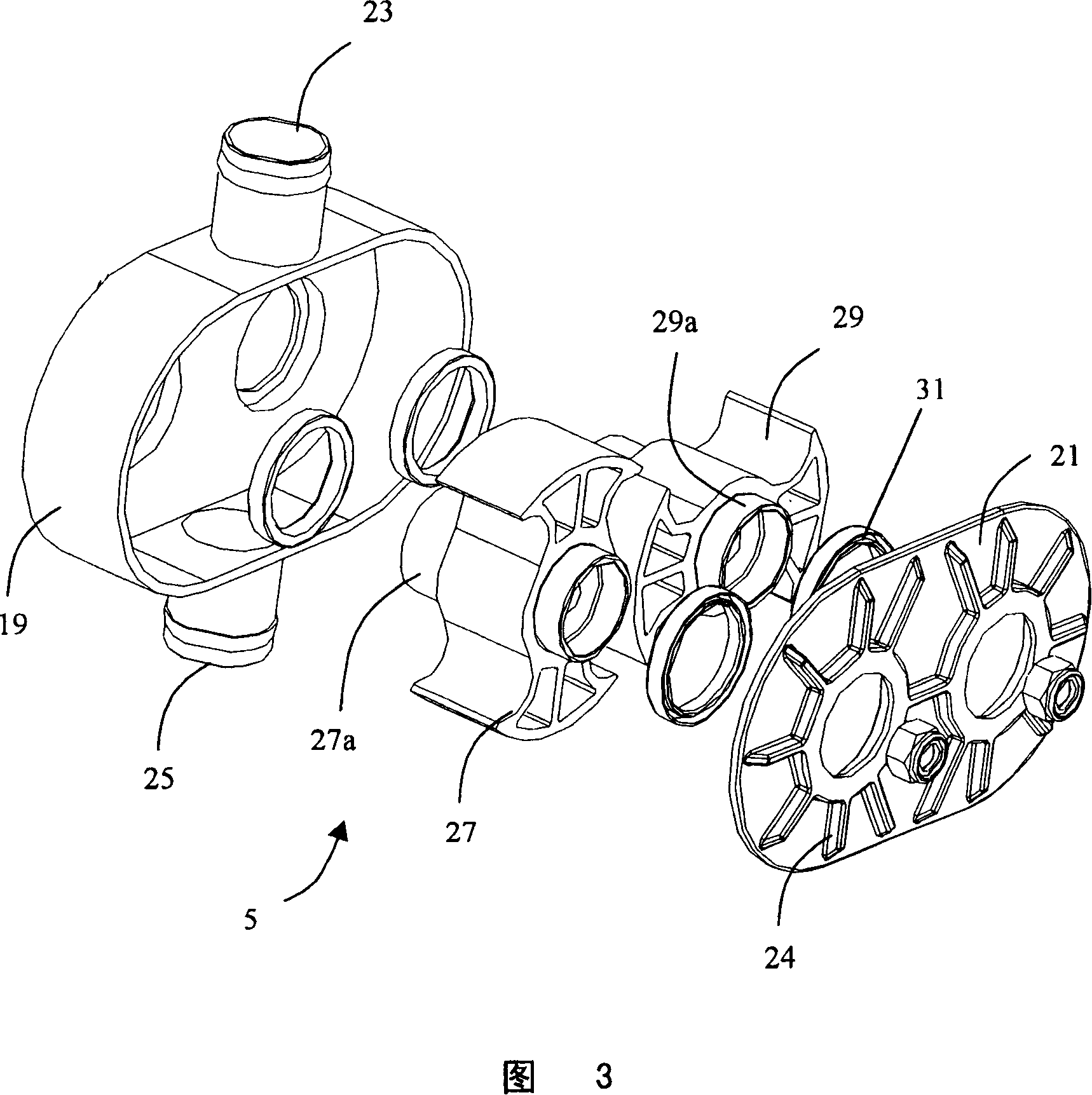
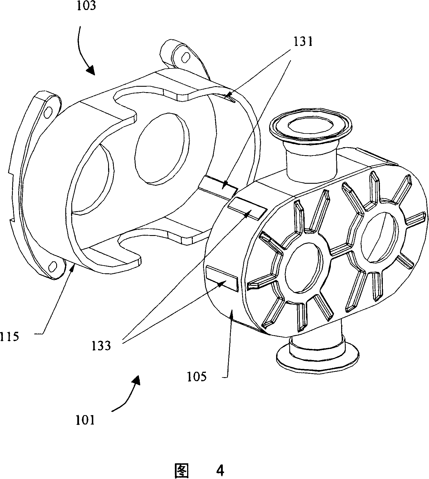
[0029] The present invention provides a rotary lobe pump including a pump body and an insert. The pump body includes the parts of the pump that normally do not come into contact with the pumped material. The insert is the plastic part that includes the parts of the pump that come into contact with the material being pumped, namely the pump chamber and the lobe rotor. The insert is housed in and supported by the outer casing of the pump body.

[0030] FIG. 1 shows a rotary lobe pump 1 according to the invention. The lobe pump 1 comprises a pump body 3 and a plastic insert 5 .

[0031] The pump body 3 includes drive means in the form of a gearbox 7 . The gearbox 7 has an output shaft 9 at its one end and two output shafts 11, 13 at its other end. The gearbox 7 is configured such that the output shafts 11, 13 rotate at the same angular velocity but in opposite directions. The output shafts 11, 13 are provided with keys (not shown in the figure) for rotationally driving other...


PUM


Abstract

The invention proposes a rotary cam pump which includes a pump body with a drive device and an outer pump housing, as well as a replaceable insert. The insert includes a box made of plastic material having an inlet end, an outlet end and an inner surface defining a pump chamber; and a pair of cam rotors configured for rotation within the pump chamber. The casing includes a bore through which the cam rotor can be rotationally driven such that the cam rotors mesh together for pumping fluid from the inlet end to the outlet end.

Description

technical field [0001] The present invention relates to a rotary lobe pump. Background technique [0002] Rotary lobe pumps are positive displacement pumps used in industry for food, pharmaceuticals, and other similar materials. When handling these materials, it is important to avoid cross-contamination and chemical interaction with other materials. [0003] Known rotary lobe pumps provide a certain provision for dismantling by the user. In this way, parts of the pump that come into contact with the pumped material can be cleaned and sanitized in batches. The problems with such cleaning and sanitizing processes are that they are time consuming and error prone. Any errors in the cleaning process can result in contamination of the pumped material and / or loss of product. [0004] Typically, the components of a rotary lobe pump are manufactured with high dimensional accuracy and low tolerances. It is especially important that the shape of the lobe rotor and pump chamber wal...

Claims


Application Information

Patent Timeline
Patent Type & Authority Applications(China)
IPC IPC(8): F04C2/14F04C15/00
CPCF04C2240/10F04C2/126F05C2225/00F04C2240/80F04C2240/30
Inventor L·毕晓普M·杨
Owner ITT MFG ENTERPRISES LLC
Learn More