Valve, especially proportional pressure control valve

A proportional relief valve and fluid technology, applied to the valve, can solve the problems of large structure space, easy failure and high manufacturing cost, so as to reduce the possibility of failure, reduce the cost of manufacturing and maintenance, and improve the reliability of operation functions. Effect

Inactive Publication Date: 2008-02-13
HYDAC FLUITECHNIK GMBH
View PDF1 Cites 25 Cited by
  • Summary
  • Abstract
  • Description
  • Claims
  • Application Information

AI Technical Summary

Problems solved by technology

Although the above functional structure is reliable in operation, it can be expected from the number of many valves that it is prone to failure during operation, which shortens the maintenance interval
Known solutions also require a lot of construction space and are expensive to manufacture due to the high number of parts

Method used


Image

  • Valve, especially proportional pressure control valve
  • Valve, especially proportional pressure control valve
  • Valve, especially proportional pressure control valve

Examples


Embodiment Construction

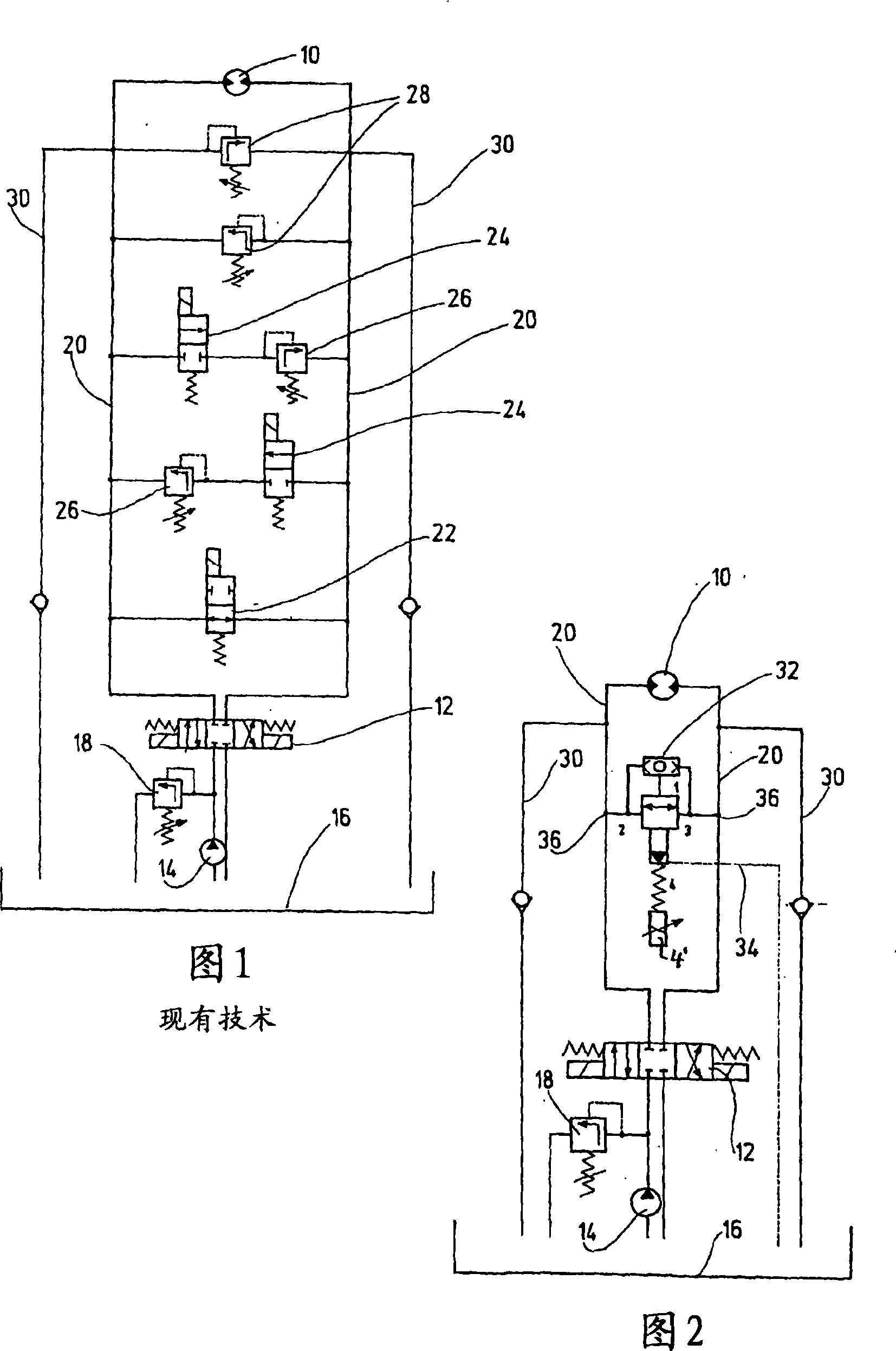
[0013] FIG. 1 shows a part of a hydrodynamic drive for a scissor lift work platform, not shown in detail, in the form of a circuit diagram. The above-mentioned means of transport usually have two axles, wherein the rear-wheel drive is generally implemented, and the front axles can be controlled separately to enable a switchable all-wheel drive, wherein the drives for the two axles are designed essentially identically. In Fig. 1 about the prior art, represent a hydraulic motor 10 as the driving device of the wheel shaft not drawn in detail for the above-mentioned means of transport, which can be turned to according to the difference of a three-position four-way reversing valve 12 switching positions Driven in both directions of rotation for forward or reverse travel and for braking functions. According to the illustration according to FIG. 1 , the 4 / 3-way directional control valve 12 is in an intermediate position and is also connected to a hydraulic pump 14 and an oil tank 16 ...


PUM


Abstract

A proportional pressure control valve includes a valve housing (38) with at least three fluid connections (1, 2, 3). The valve can be connected to a hydraulic drive system with a pre-determinable consumer pressure. The valve can perform reliable valve switching functions even for low-viscous fluid media, and can reduce its susceptibility to disturbance variables. A valve piston (56) actively connected to a pilot seat (5) by an energy accumulator (62) can be controlled by a control device (40). The consumer pressure on a fluid connection (1) acts on the valve piston (56) such that, according to the consumer pressure and the actuating force of the control device (40), a fluid can flow between the two other fluid connections (2 and 3) in both directions inside the valve housing (38).

Description

technical field [0001] The invention relates to a valve, in particular a proportional overflow valve, having a valve housing with at least three fluid connections, wherein the valve can be connected to a hydraulic drive system with a defined operating pressure. Background technique [0002] A proportional pressure regulating valve is known (US Pat. No. 4,316,599), which forms a control valve for hydraulic systems and which provides a substantially constant output pressure in the event of a varying input pressure. The output pressure to be controlled is given by a current signal supplied by a corresponding electronic control unit and acts on an actuating magnet as a magnetic force system. The steering magnet can be made as a pressure-tight oil sump magnet and has a long service life. [0003] The above-mentioned proportional pressure regulating valve can be a directly controlled three-channel piston slide valve, that is, a pressure safety device with an output end. Among ot...

Claims


Application Information

Patent Timeline
Patent Type & Authority Applications(China)
IPC IPC(8): G05D16/20F15B13/044
CPCF16K17/0473G05D16/18G05D16/166F16K17/105F16K17/22F15B13/0433F15B13/024F16H61/4148F16H61/4043G05D16/2093G05D16/101G05D16/2097G05D16/2024Y10T137/87917Y10T137/86702Y10T137/7771Y10T137/86614F15B13/044
Inventor P·布鲁克H·阿尔贝特
Owner HYDAC FLUITECHNIK GMBH
Why Eureka
Try Eureka