
Positioning device with positioning unit capable of linearity moving

A technology of positioning device and positioning unit, which is applied to electrical components, manufacturing tools, electrical components, etc., can solve the problems of affecting positioning accuracy and deterioration of vibration characteristics, and achieve the effects of saving space, reducing mass, and avoiding transitional oscillations.

Inactive Publication Date: 2008-02-13
SIEMENS ELECTRONICS ASSEMBLY SYST LLC
View PDF3 Cites 1 Cited by
  • Summary
  • Abstract
  • Description
  • Claims
  • Application Information

AI Technical Summary

Problems solved by technology

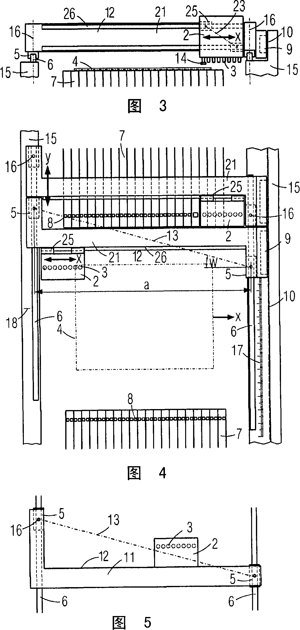
[0004] In order to alleviate this situation, in another positioning arm according to EP940229A1, elastic compensating elements are arranged between the bearing element and the positioning arm, which affect the positioning accuracy and degrade the vibration behavior

Method used


Image

  • Positioning device with positioning unit capable of linearity moving
  • Positioning device with positioning unit capable of linearity moving

Examples


Embodiment Construction

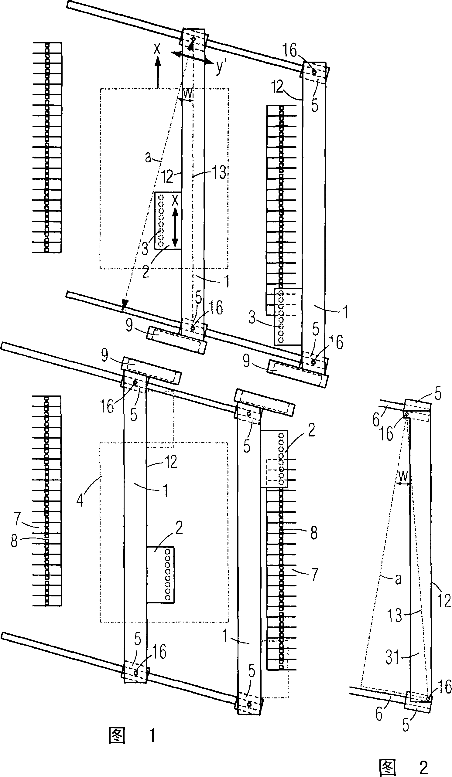
[0026] FIG. 1 shows the main functional unit of a equipping device with two equipping areas for substrates 4 arranged one behind the other in the transport direction x and with component transport mechanisms 7 arranged on their sides, which transport mechanisms have The components 14 aligned in the transport direction x are removed from the position 8 .

[0027] Above the two installation areas and the removal position 8, there are two slightly longer first positioning arms 1 oriented in the transport direction x, which can each be guided by a corresponding coil part 9 of a linear motor on mutually parallel stationary guide rails. 6 moves. The guide rail 6 in the form of a track extends obliquely with respect to the conveying direction in a first transverse direction y'. The first positioning arm 1 is guided at each end by means of a bearing 5 without play in one of the rail-shaped guide rails 6 .

[0028] The bearing 5, for example composed of a ball circulating element, ha...


PUM


Abstract

The device has two guideways, arranged parallel to each other, defining a guiding section. Positioning arms (1) are anchored at supports (5) and extends between the supports. The positioning arms are swivellably supported at hinge axes (16), which are perpendicular to the guiding section, in the area of the supports of the guideways. A connection axis runs between the hinge axes and transverse to the guideways.

Description

technical field [0001] The invention relates to a positioning device, in particular for handling electrical components, having two parallel guide rails defining a guide plane and bearings guided linearly displaceable thereon, to which positioning units are fastened. Background technique [0002] EP 0 962 125 B1 discloses a one-sidedly guided and driven elongated positioning arm, in which the oppositely arranged free projecting end can oscillate without damping, so that a correspondingly highly dynamic positioning process is delayed by a damping period. This positioning arm requires at least 3 bearing or support elements. In order to reduce such transient oscillations, such a positioning arm must have the greatest possible bending stiffness, which increases its own weight and increases the driving or braking power when acceleration is required. [0003] US Pat. No. 5,002,448 A discloses a positioning arm guided on both sides, in which the connection axis runs perpendicular t...

Claims


Application Information

Patent Timeline
Patent Type & Authority Applications(China)
IPC IPC(8): H05K13/00H05K13/04B25J9/02
CPCB25J9/026H05K13/0015H05K13/0413H05K13/0406H05K13/0404
Inventor U·科勒
Owner SIEMENS ELECTRONICS ASSEMBLY SYST LLC
Learn More