

Assembly head comprising a stepped-drive rotating rotor and a pneumatic pressure control device
一种装配头、转子的技术,应用在电气元件、电气元件等方向,能够解决降低真空源10真空效率、小压差、不能可靠分析等问题
- Summary
- Abstract
- Description
- Claims
- Application Information
AI Technical Summary
Problems solved by technology
Method used
Image

Examples
Embodiment Construction
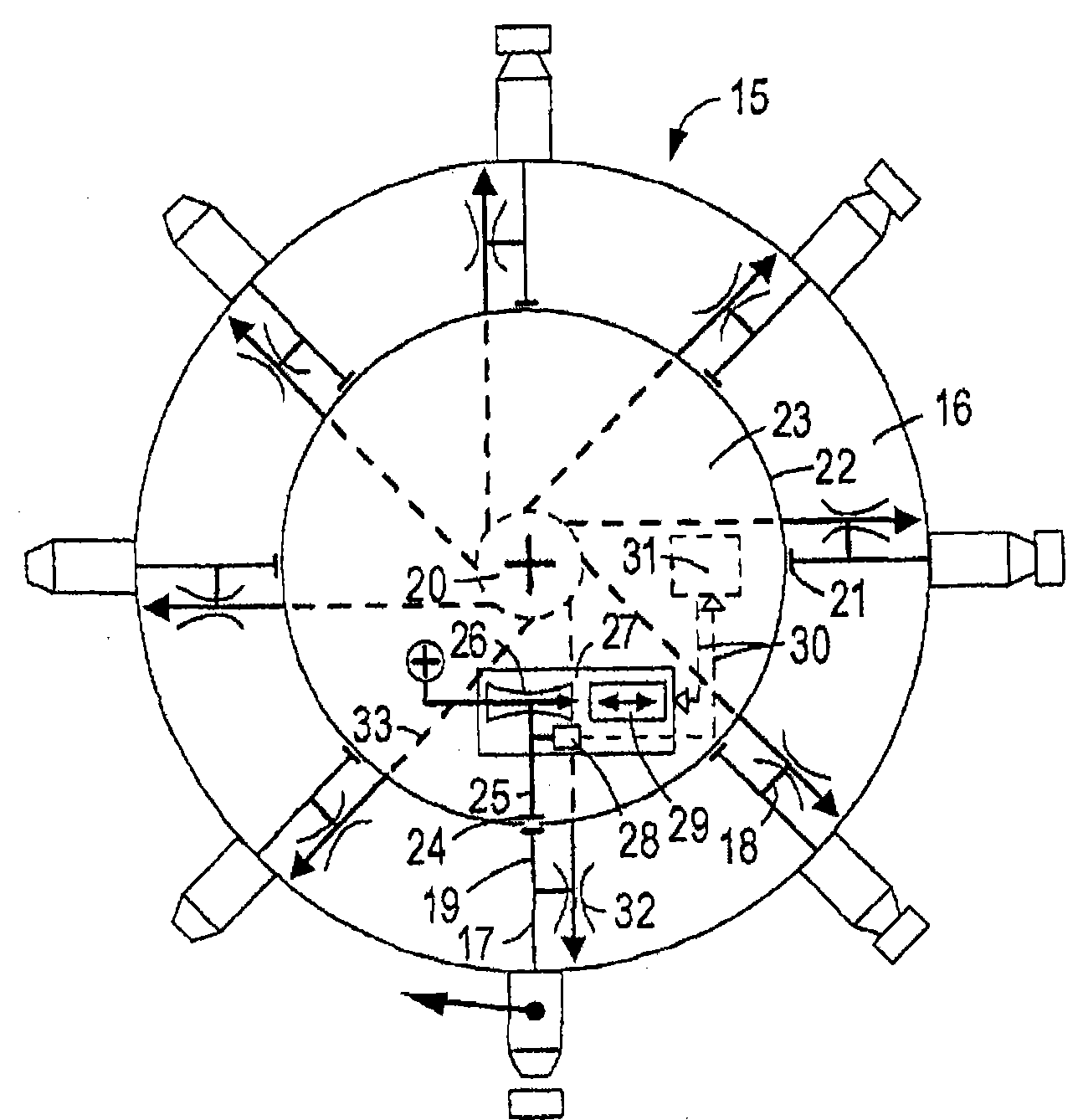
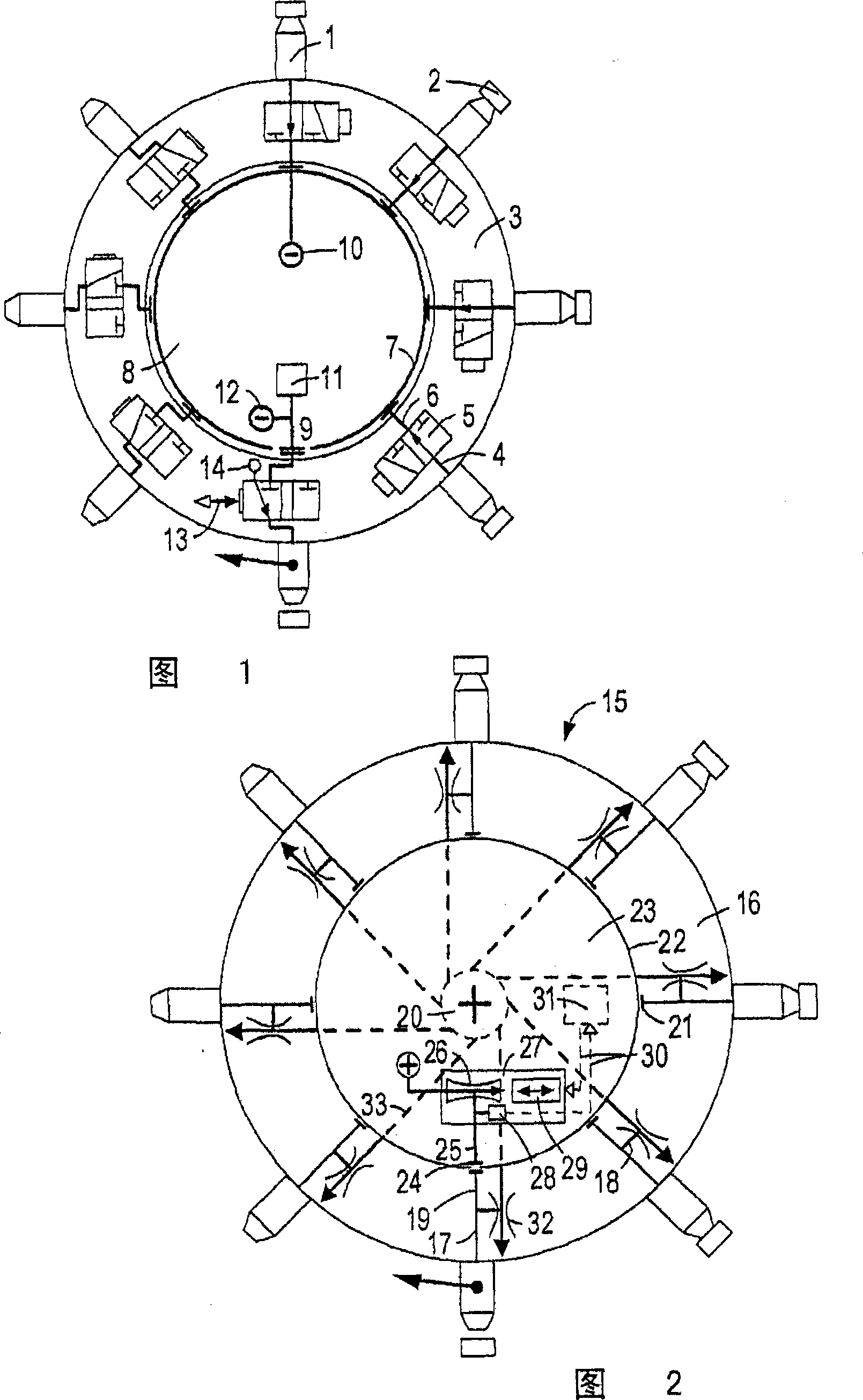
[0022] According to FIG. 2 , an assembly head 15 modified according to the invention likewise has suction pipes 1 spaced apart in a star pattern on a rotor 16 . The suction pipes 1 are connected to respective pneumatic conduits 17 which branch into suction conduits 18 and control conduits 19 . The whole suction pipe 18 is connected with jet pumps 32 which are respectively fixed on the rotors and rotates simultaneously. The jet pumps 32 are permanently and directly connected to the central high-pressure pipe 20 of the rotor 16 through the connection pipes, and generate a permanent vacuum in the suction pipes.
[0023] The control lines 19 lead into respective bores 21 of the rotor 16 which are closed by circular slide valves 22 of the stator 23 . The stator has, at the lower mounting position of the suction pipe 1 , a slide valve opening 24 complementary to the bore 21 , which is passed through a fixed control line 25 and an internal jet pump 26 formed as a flow meter nozzle of...
PUM
 Abstract
Description
Claims
Application Information