Assembly head comprising a stepped-drive rotating rotor and a pneumatic pressure control device

A technology for assembling heads and rotors, applied in electrical components, electrical components, etc., can solve the problems of small pressure difference, unreliable analysis, and reduction of vacuum efficiency of vacuum source 10

Inactive Publication Date: 2008-02-20
ASM ASSEMBLY SYST GMBH & CO
View PDF1 Cites 1 Cited by
  • Summary
  • Abstract
  • Description
  • Claims
  • Application Information

AI Technical Summary

Problems solved by technology

Because the suction tube 1 adapts its suction hole to components of different sizes, especially small components generate a small pressure difference, which can be superimposed by the effects of environmental influences and thus cannot be analyzed reliably
If the component cannot be removed or is later lost, the gap reduces the vacuum efficiency of the vacuum source 10

Method used


Image

  • Assembly head comprising a stepped-drive rotating rotor and a pneumatic pressure control device

Examples


Embodiment Construction

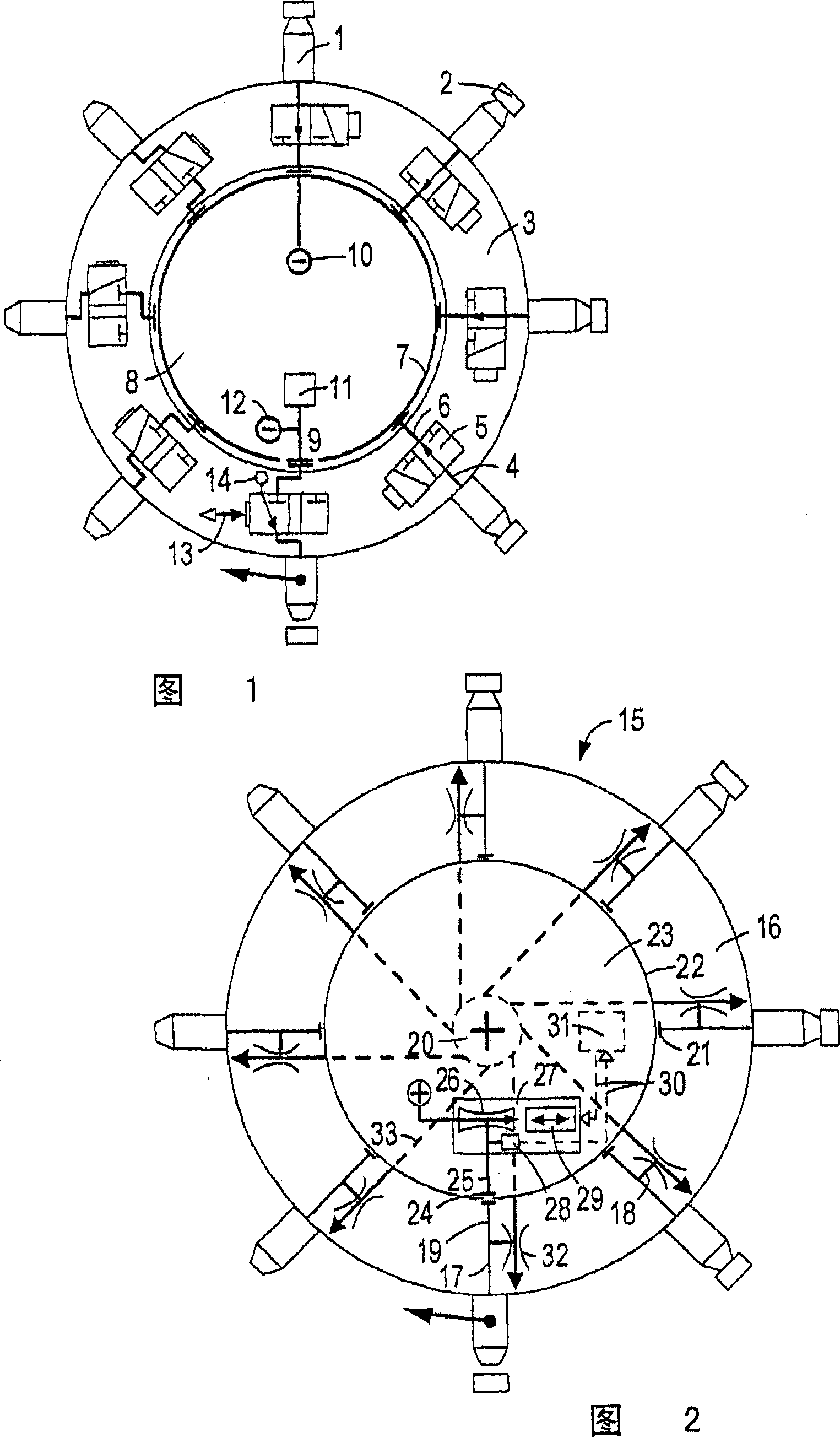
[0022] According to FIG. 2 , an assembly head 15 modified according to the invention likewise has suction pipes 1 spaced apart in a star pattern on a rotor 16 . The suction pipes 1 are connected to respective pneumatic conduits 17 which branch into suction conduits 18 and control conduits 19 . The whole suction pipe 18 is connected with jet pumps 32 which are respectively fixed on the rotors and rotates simultaneously. The jet pumps 32 are permanently and directly connected to the central high-pressure pipe 20 of the rotor 16 through the connection pipes, and generate a permanent vacuum in the suction pipes.

[0023] The control lines 19 lead into respective bores 21 of the rotor 16 which are closed by circular slide valves 22 of the stator 23 . The stator has, at the lower mounting position of the suction pipe 1 , a slide valve opening 24 complementary to the bore 21 , which is passed through a fixed control line 25 and an internal jet pump 26 formed as a flow meter nozzle of...


PUM


Abstract

The assembly head (15) has a holding circuit delivering a permanent vacuum to all suction tubes (1). In the installation - or extraction position, the respective suction line is additionally connected to a fixed regulating valve whose effective pressure can be superimposed on the permanent vacuum and adjusted between overpressure and underpressure. As a result, the process reliability of the assembly head can be significantly increased.

Description

[0001] This application is a divisional application with the title of invention "Assembly head with step-rotatable rotor and pneumatic pressure control device" and application number 2002811325X. technical field [0002] The invention relates to an assembly head walkable on linear guides, with a stator and a stepwise rotatable rotor, with a plurality of suction tubes for sucking in electronic components, wherein the suction tubes are connected to pneumatic pipes; each suction tube can Access to the installation-or extraction position; the suction pipe in this position is subjected to a pneumatic pulse via the control valve and can be connected to a fixed pipeline by means of a circular slide valve. Background technique [0003] EP 0 879 550 B1 discloses a control valve designed as a mechanically actuated directional valve, via which the suction line is selectively connected to vacuum or compressed air. In this respect, it is common to store vacuum threshold values ​​for diff...

Claims


Application Information

Patent Timeline
Patent Type & Authority Applications(China)
IPC IPC(8): H05K13/04
CPCH05K13/0408H05K13/0409H05K13/082H05K13/041H05K13/04
Inventor S·博格尔R·迪贝尔
Owner ASM ASSEMBLY SYST GMBH & CO
Why Eureka
Try Eureka