
Overload safeguard for tensometer

A push-pull force gauge and overload protection technology, which is applied in the direction of applying stable tension/pressure to test the strength of materials, and can solve problems such as loss and damage of push-pull force gauges

Inactive Publication Date: 2008-02-27
KINPO ELECTRONICS
View PDF1 Cites 4 Cited by
  • Summary
  • Abstract
  • Description
  • Claims
  • Application Information

AI Technical Summary

Problems solved by technology

[0003] During the operation of measuring or testing the push-pull force of the product with a tension meter, the push-pull force meter is often damaged due to the push and pull force exceeding the load range of the tension meter, resulting in losses.

Method used


Image

  • Overload safeguard for tensometer
  • Overload safeguard for tensometer

Examples


Embodiment Construction

[0020] For other purposes and effects of the present invention, please refer to the accompanying drawings and the embodiments, which are described in detail as follows.

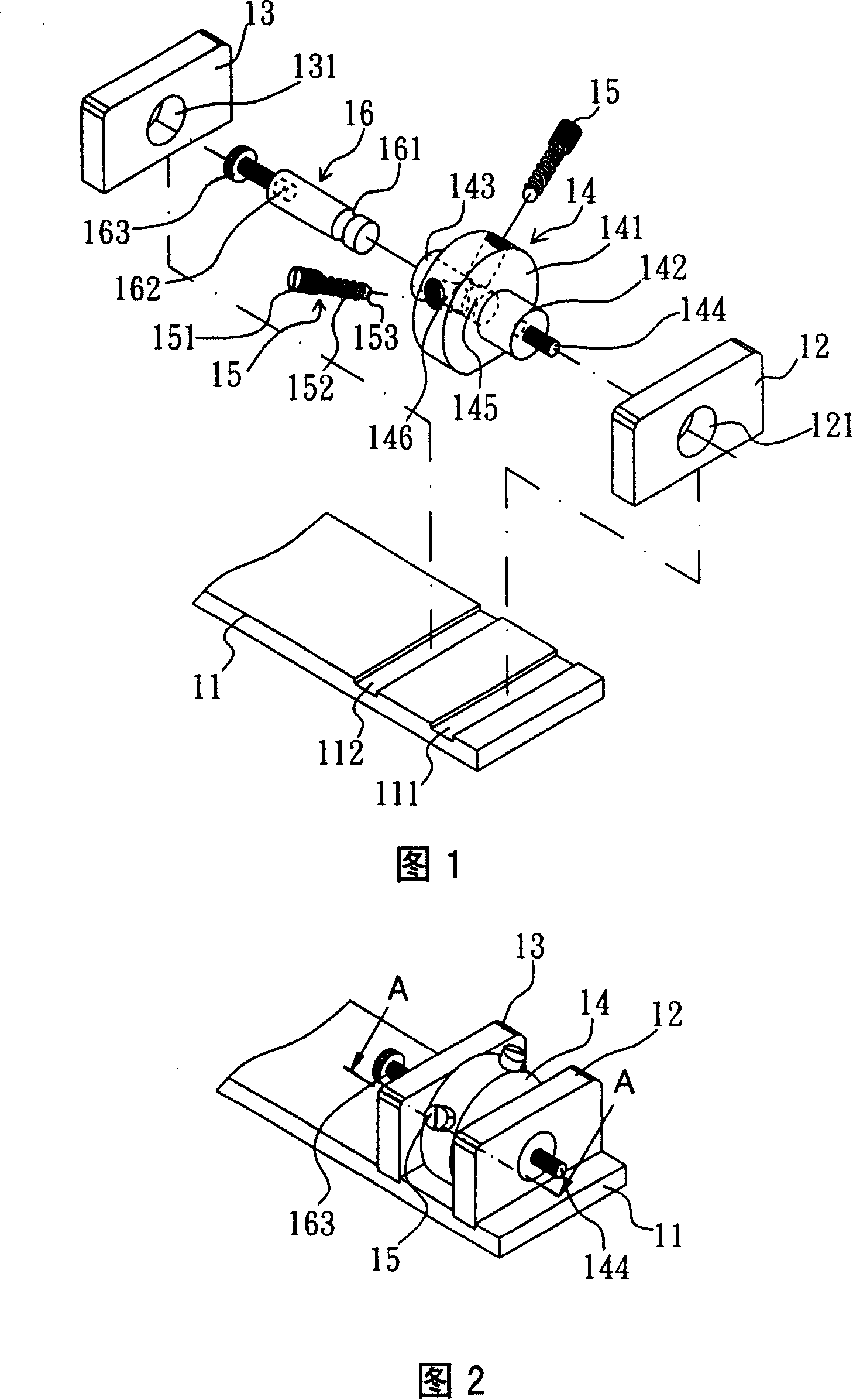
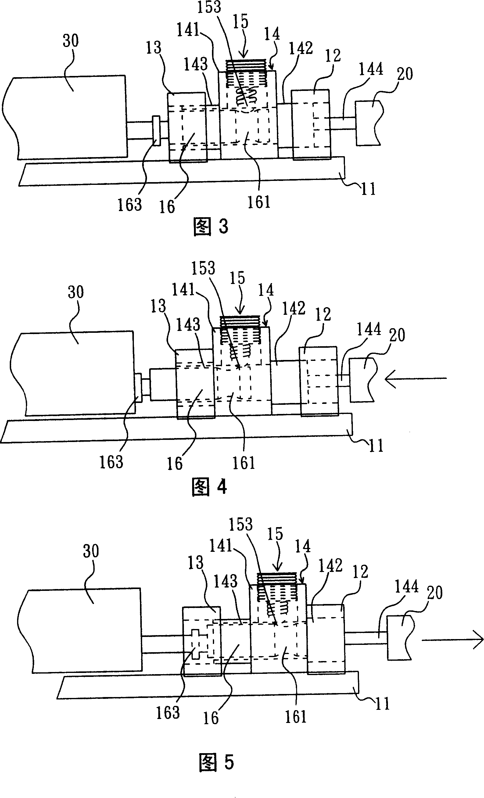
[0021] Please refer to Figures 1 and 2. The embodiment of the push-pull dynamometer overload protection device of the present invention is used to place between the push-pull force source and the push-pull dynamometer to protect the push-pull dynamometer, including:

[0022] A bottom plate 11, which has a first groove 111 and a second groove 112 on its top;

[0023] A first block 12 has a penetration hole 121; the bottom of the first block 12 is placed in the first groove 111 of the bottom plate 11, and is fixedly combined with the bottom plate 11;

[0024] A second block 13 has a penetration hole 131; the bottom of the second block 13 is placed in the second groove 112 of the bottom plate 11, and is fixedly combined with the bottom plate 11;

[0025] A main body 14 has a middle part 141, a first columnar p...


PUM


Abstract

The invention is an overload protection device of push-pull effort gauge, comprising of base plate, the first block, the second block, main body, and at least one flexible component and cylindrical body, use the ball bottom of the flexible component to stretch into groove of the cylindrical body, so that the cylindrical body and the main body are linked together to provide a pushing and pulling force when the push-pull effort gauge measure the force source; when the pushing and pulling force the force source imposed to main body exceed the force which the bottom of the flexible component can be placed in the groove, the bottom of the flexible component will escape the groove, so that the cylindrical body will get loose from the main body, the push-pull effort gauge will not be exposed great pushing and pulling force, avoid damage of push-pull effort gauge caused by overload operation in the process of measurement, and can reduce the cost during the products research and development due to damage of push-pull effort gauge.

Description

technical field [0001] The invention relates to a push-pull force overload protection device, in particular to an overload protection device for a push-pull force gauge. Background technique [0002] In the development process of general electronic products, in order to test the durable state of the product, various stress state tests will be carried out. The applicant has been approved for various measuring and testing devices, such as the improved structure of the elastic measuring device disclosed in Taiwan New Patent No. M250143; the retractable object that can set the push-pull force disclosed in Taiwan Patent Publication No. 00506531 Life testing equipment, etc. [0003] In the operation process of measuring or testing the push-pull force of the product with a tension meter, the push-pull force meter is often damaged due to the push and pull force exceeding the load range of the tension meter, resulting in losses. Contents of the invention [0004] In order to prev...

Claims


Application Information

Patent Timeline
Patent Type & Authority Applications(China)
IPC IPC(8): G01N3/08
Inventor 陈忠贤
Owner KINPO ELECTRONICS
Learn More