Method of controlling vacuum cleaner

A technology for vacuum cleaners and dust, applied in the direction of vacuum cleaners, suction filters, suction nozzles, etc., can solve the problems of vacuum cleaner suction efficiency (decrease of suction force, etc.), and achieve the effect of uniform suction force

Inactive Publication Date: 2008-03-12
LG ELECTRONICS INC
View PDF0 Cites 7 Cited by
  • Summary
  • Abstract
  • Description
  • Claims
  • Application Information

AI Technical Summary

Problems solved by technology

[0010] At this time, when the amount of dust collected in the dust collection unit increases, the suction efficiency (suction force) of the vacuum cleaner decreases

Method used


Image

  • Method of controlling vacuum cleaner
  • Method of controlling vacuum cleaner
  • Method of controlling vacuum cleaner

Examples


Embodiment Construction

[0040] Reference will now be made in detail to the preferred embodiments of the invention, examples of which are illustrated in the accompanying drawings. Wherever possible, the same reference numbers will be used throughout the drawings to refer to the same or like parts.

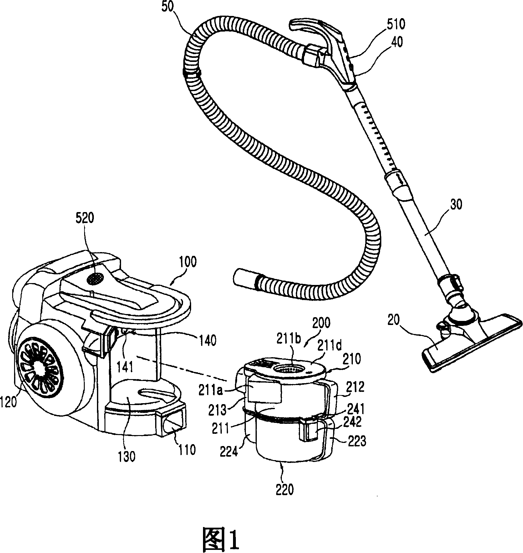
[0041] FIG. 1 is a perspective view of a dust collection unit of a vacuum cleaner according to an embodiment of the present invention when the dust collection unit is separated from the vacuum cleaner.

[0042] Referring to FIG. 1 , the vacuum cleaner includes a main body 100 in which a suction generating unit for generating vacuum pressure in the vacuum cleaner and a dust collecting unit 200 for separating and storing dust in gas are provided.

[0043] The vacuum cleaner includes a suction nozzle 20 that sucks dust-containing gas, a handle 40 that allows a user to manipulate the operation of the vacuum cleaner, an extension pipe 30 that connects the suction nozzle 20 to the handle 40, and connects the suc...


PUM


Abstract

There is provided a method of controlling a vacuum cleaner having a dust collection unit in which dusts separated from air sucked by a suction motor are stored. The method includes operating the suction motor with a first driving force, determining an amount of the dusts stored in the dust collection unit, and operating the suction motor with a second driving force greater than the first driving force as the amount of the dusts increases.

Description

technical field [0001] The present invention relates to a control method of a vacuum cleaner, and more particularly, to a vacuum cleaner capable of allowing the vacuum cleaner to suck dust with a uniform suction force by changing the driving force of a suction motor according to the amount of dust stored in a dust collection unit. Control Method. Background technique [0002] Generally, a vacuum cleaner is a device capable of sucking dust-containing gas using vacuum pressure installed in a main body and filtering the dust in the main body. [0003] Vacuum cleaners are divided into tank type and column type. The canister type vacuum cleaner includes a main body and a suction nozzle connected to the main body through a connecting pipe. The upright type vacuum cleaner includes a main body and a suction port integrally formed with the main body. [0004] Meanwhile, the dust collection unit installed in the cyclone type vacuum cleaner separates the dust from the gas using the ...

Claims


Application Information

Patent Timeline
Patent Type & Authority Applications(China)
IPC IPC(8): A47L9/28A47L9/02A47L9/16
CPCA47L9/2836A47L9/281A47L9/19A47L9/2857A47L9/2842A47L9/2889A47L9/108A47L9/00A47L9/28
Inventor 河建镐徐真旭尹昌虎金镇泳李昌勋朴润熙
Owner LG ELECTRONICS INC
Why Eureka
Try Eureka