Elevator gate control device

A door control and elevator hall technology, which is applied in the field of elevator hall door control devices, can solve the problems of accidents, maintenance workers and installers easily falling into the elevator shaft, etc., and achieves the effect of simple structure

Inactive Publication Date: 2008-03-12
黄志成
View PDF0 Cites 0 Cited by
  • Summary
  • Abstract
  • Description
  • Claims
  • Application Information

AI Technical Summary

Problems solved by technology

[0002] At present, during the installation and maintenance of the elevator, the hall door is opened by the key, and the two doors are fully open. During the construction and maintenance process, when the hall door is fully open, the maintenance workers and installers are likely to fall down the elevator shaft and cause accidents.

Method used


Image

  • Elevator gate control device

Examples


specific Embodiment approach

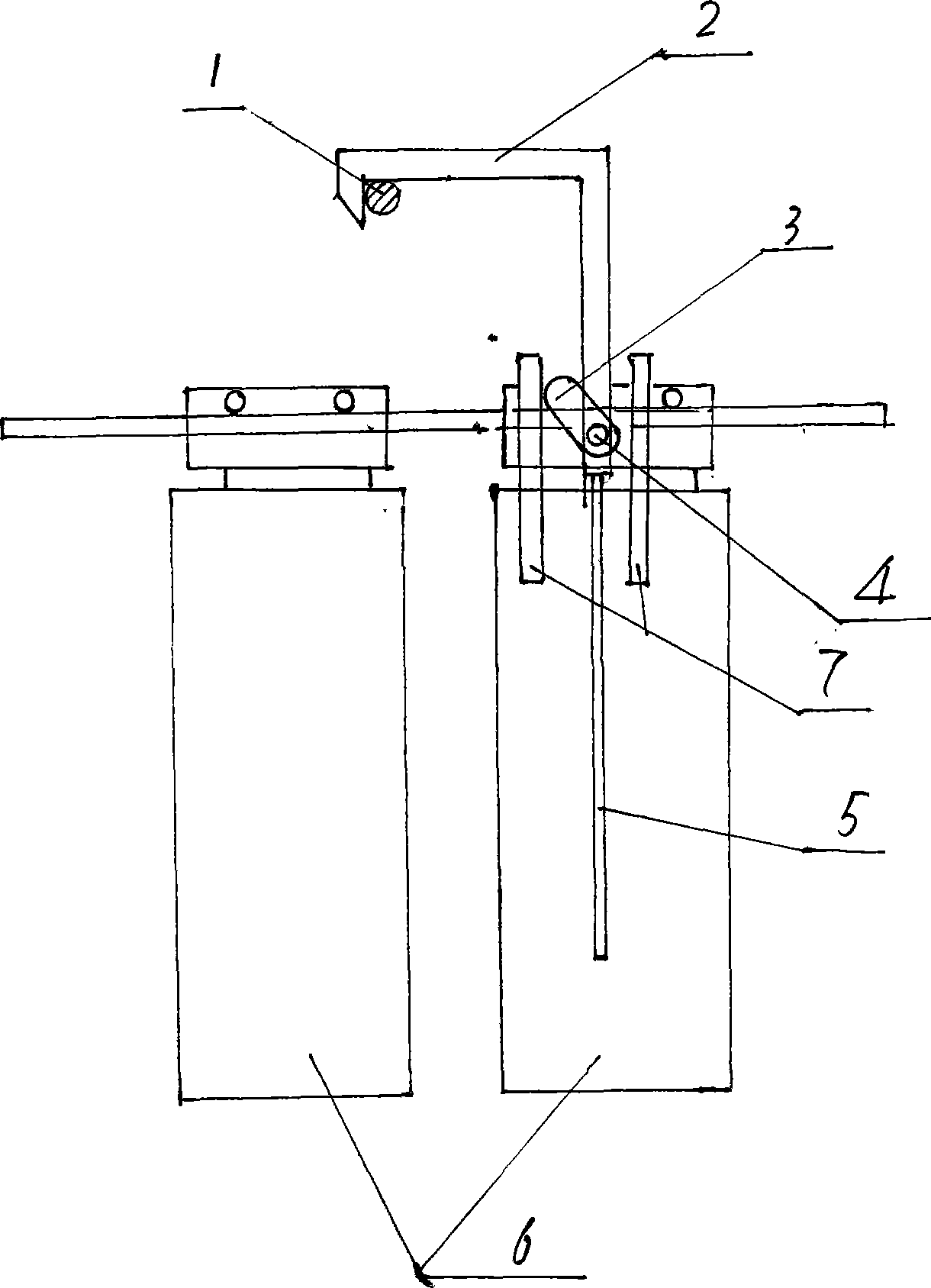
[0010] In the figure, the hall door (6) is equipped with a fixed shaft (4), and one end of the positioning fish (2) rotates around the fixed shaft (4). Block (3), the other end is fish-shaped, and a retaining shaft (1) is installed on the wall, and the retaining shaft (1) is installed at the center 5-10mm away from the hall door. Restricted by the position and size of the retaining shaft (4), it can only be opened by 10-20mm, which restricts the personnel's body from entering the elevator shaft. Since it is opened to a certain width, it is convenient for personnel to visit the position of the elevator car and avoids the absence of the elevator car. The position of the hall door will cause the danger of people falling and avoid the occurrence of safety accidents.

[0011] When the elevator car goes up or down on the same floor as the hall door, when the car door is opened, the door knife (7) drives the wedge (3) to cause the positioning hook (2) to rotate around the fixed shaft...


PUM


Abstract

The present invention relates to a control device for a lift landing door. The landing door is provided with a positioning hook, one end of the positioning hook rotates around a fixed shaft, a cheese block is fixed, and a retaining shaft is arranged 5-10mm away from the center of the landing door; a manual operation rod is fixed on one end of the positioning hook; the present invention can be widely used in the lift.

Description

1. Technical field [0001] The invention belongs to an elevator control device, in particular to an elevator hall door control device. 2. Background technology [0002] At present, during the installation and maintenance of the elevator, the hall door is opened by a key, and the two doors are fully open. During construction and maintenance, when the hall door is fully open, maintenance workers and installers are likely to fall down the elevator shaft, causing accidents. 3. Contents of the invention [0003] In order to overcome the above defects, the utility model provides an elevator hall door control device, which has a simple structure and reliable operation. [0004] The technical solution adopted by the present invention to solve the technical problems is: the hall door has a positioning hook, one end of which is rotated around a fixed shaft, and a wedge is fixed, and a retaining shaft is arranged, and the retaining shaft is installed 5-10 mm away from the center of th...

Claims


Application Information

Patent Timeline
Patent Type & Authority Applications(China)
IPC IPC(8): B66B13/00
Inventor 黄志成
Owner 黄志成
Why Eureka
Try Eureka