Working machinery

A technology for operating machinery and operating devices, which can be applied to earth movers/shovels, construction, etc., and can solve the problems of smaller inspection openings, increased operator burden, and reduced workability

A technology for operating machinery and operating devices, which can be applied to earth movers/shovels, construction, etc., and can solve the problems of smaller inspection openings, increased operator burden, and reduced workability

CN101139844AActive Publication Date: 2008-03-12NIHON KENKI CO LTD

Image

  • Working machinery
  • Working machinery
  • Working machinery

Examples


Embodiment Construction

[0033] Hereinafter, a case in which the working machine according to the embodiment of the present invention is applied to a hydraulic excavator will be described in detail with reference to the drawings.

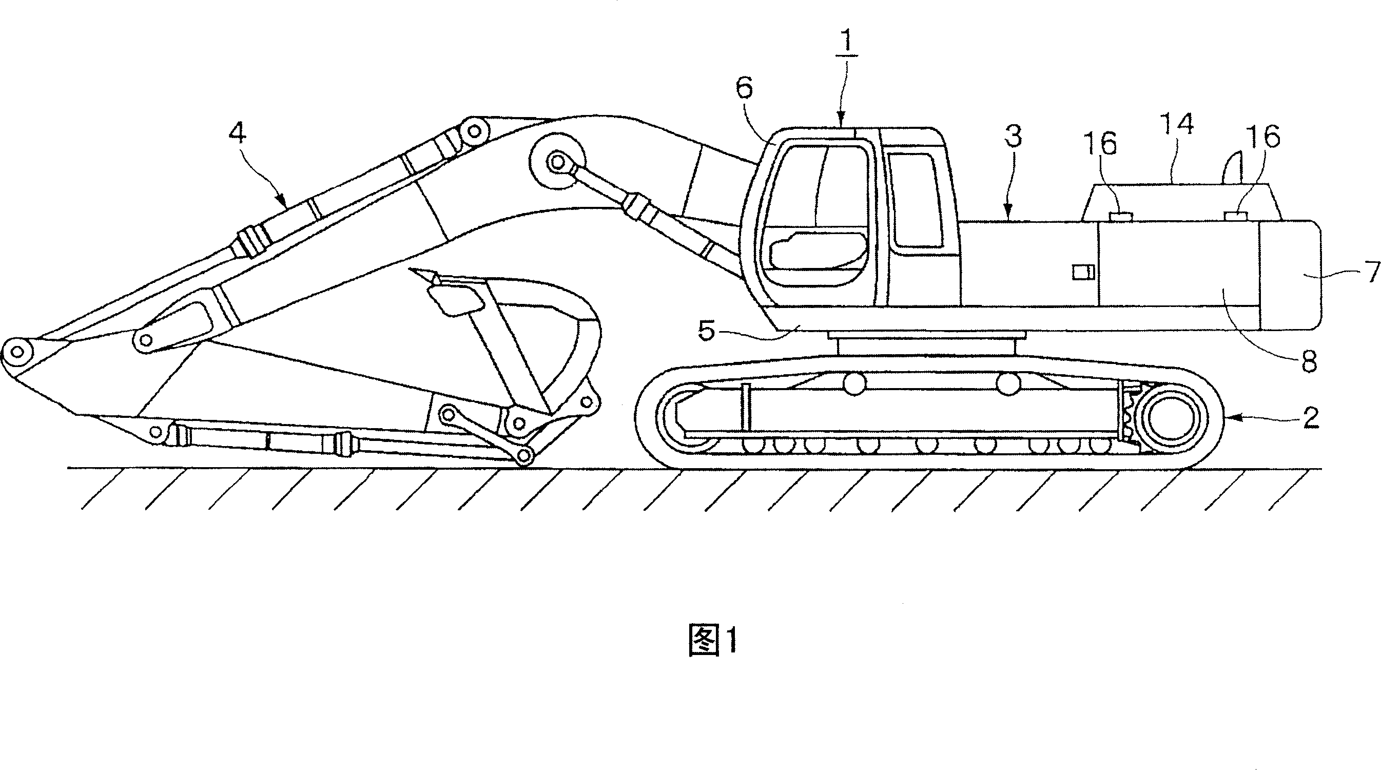
[0034] Here, FIGS. 1 to 11 show a first embodiment of the present invention. In the figure, reference numeral 1 is a hydraulic excavator as a working machine, and the general structure of the hydraulic excavator 1 includes: a crawler-type undercarriage 2 that can automatically travel as shown in Figure 1; 2 on the upper rotating body 3 ;

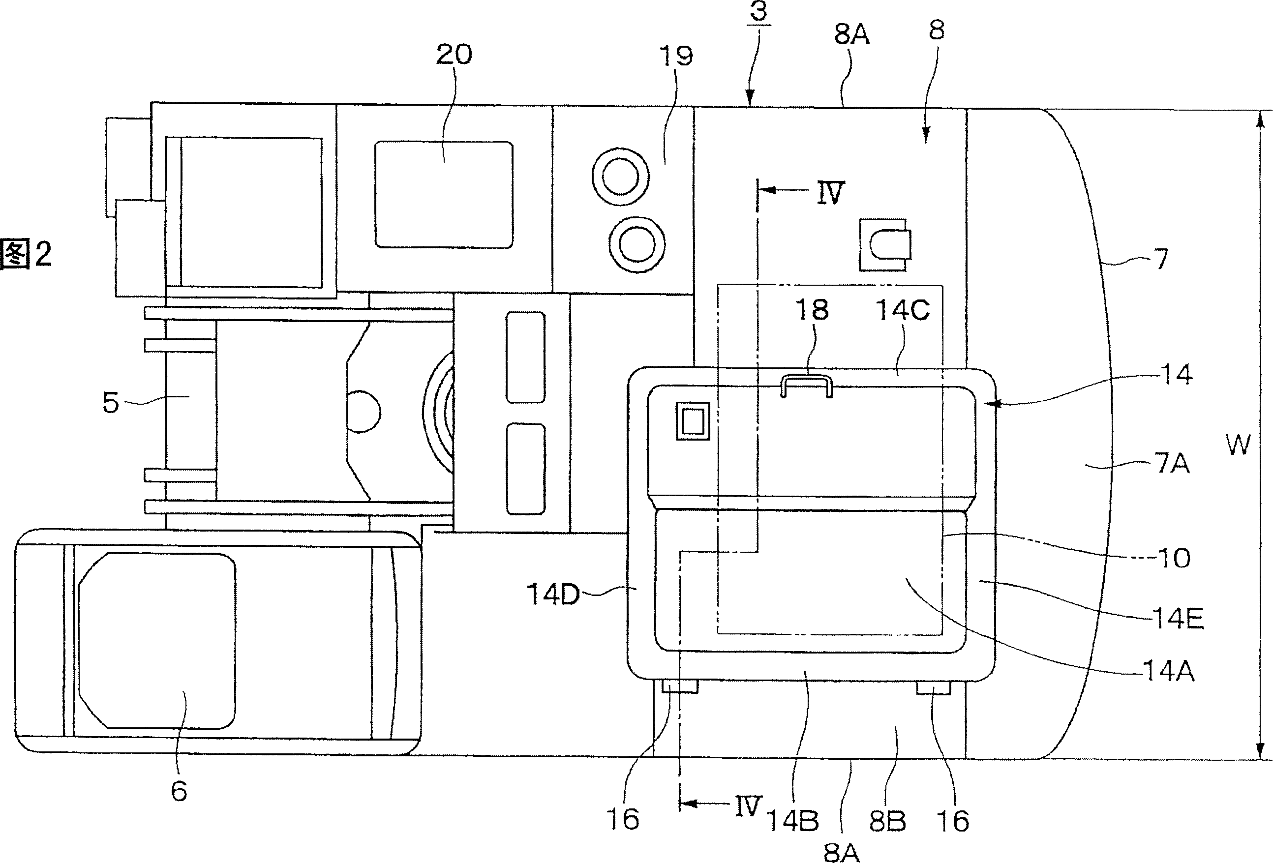
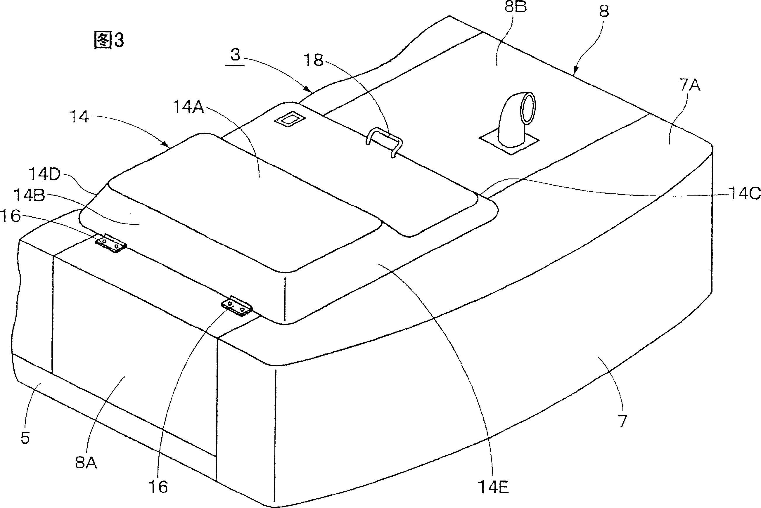
[0035]In this case, the upper turning body 3 of the hydraulic excavator 1 together with the lower traveling body 2 constitutes a vehicle body of the working machine. Further, the upper turning body 3 is constituted by a turning frame 5 , a cab 6 , a counterweight 7 , a roof 8 , an engine 10 , an engine cover 14 , and the like which will be described later. In addition, the vehicle width of the upper turning body 3 is set to a dimension ...


PUM


Abstract

To hold an engine cover in a door opening state by operation of only one hand, and to ensure a large opening angle in the door opening state.A guide hole 28 made from a long linear guide portion 28A and a V-shaped guide 28B is provided on a stay guide 27 of a door opening holding mechanism 21. A first bending portion 28B1 of the V-shaped guide portion 28B is formed so as to curve along a moving track 25 when a tip end side of a stay 22 rises and falls at a position on an opposite side to the linear guide portion 28A. A second bending portion 28B2 is formed from an end portion of the first bending portion 28B1 to have a shape which is generally bent in a V-shape, and extends outward in a diameter direction of the moving track 25 in regard to the first bending portion 28B1. When the engine cover 14 is held in the door opening state, the tip end side of the stay 22 is hooked to the second bending portion 28B2 to be locked.

Description

technical field [0001] The present invention relates to a work machine suitable for use as a construction machine such as a hydraulic excavator, a crane, a wheel loader, a forklift, or a transport machine, and more particularly to a work machine provided with a roof for accommodating a power source such as an engine. Background technique [0002] In general, working machines (construction machines) such as hydraulic excavators have a structure in which a roof is provided on the frame of the vehicle body, and a machine room that accommodates a power source such as an engine is formed inside by the roof. In addition, the structure adopted is: an opening for inspection of the engine in the maintenance and inspection machine room is provided on the roof top, and the opening is covered by the engine cover (engine cover) in a switchable manner (for example, refer to Patent Document 1-Specific Publication No. 2001-180526). [0003] In addition, between the above-mentioned hood and...

Claims


Application Information

Patent Timeline
12 Mar 2008
Publication
CN101139844A
IPC
E02F9/00
CPC
E02F9/0891; E02F9/0866; E02F9/00; E02F9/08; E02F9/18
Inventors
津久井洋; 熊谷博