Glue dropping method

A technology of dispensing and dispensing device, applied in installation, optics, instruments, etc., can solve the problems of large amount of glue, affecting the quality of lens module, uneven dispensing, etc., and achieve the effect of uniform dispensing

Inactive Publication Date: 2008-03-12
HONG FU JIN PRECISION IND (SHENZHEN) CO LTD +1
View PDF0 Cites 6 Cited by
  • Summary
  • Abstract
  • Description
  • Claims
  • Application Information

AI Technical Summary

Problems solved by technology

Therefore, when the lens module first rotates, the amount of glue coated on the spacer ring is larger than the amount of glue after the rotation is stable, resulting in uneven dispensing, affecting the quality of dispensing, and even affecting the quality of the lens module

Method used


Image

  • Glue dropping method
  • Glue dropping method
  • Glue dropping method

Examples


Embodiment Construction

[0014] The following example illustrates a dispensing method that can improve the uniformity of dispensing of the lens module.

[0015] The dispensing method of the first embodiment includes the following steps.

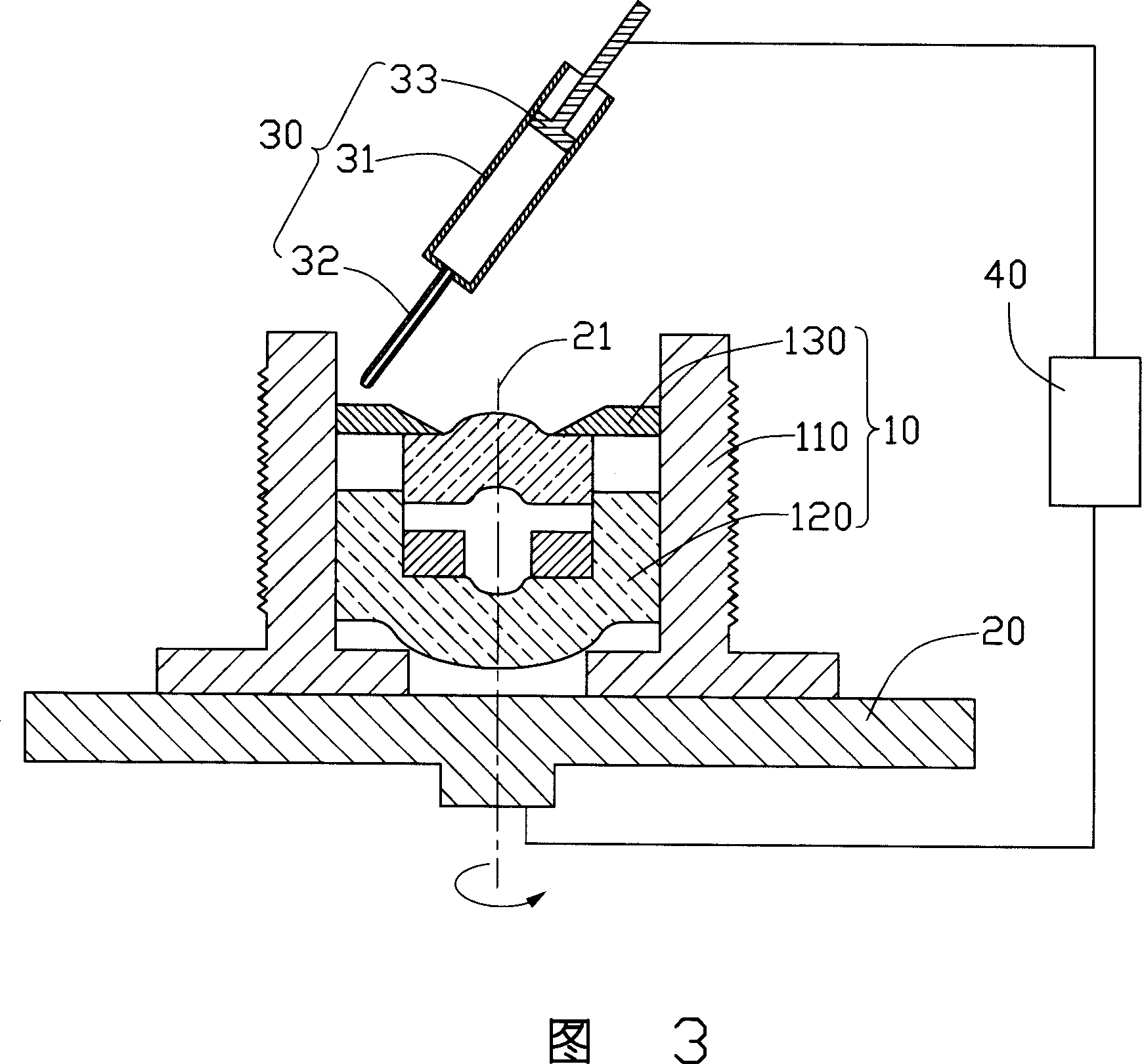
[0016] In the first step, a lens module 10 to be glued and a glue dispensing device 30 are provided.

[0017] Referring to FIG. 3 , the lens module 10 to be glued includes a lens barrel 110 , a lens group 120 and a spacer ring 130 . The lens group 120 and the spacer ring 130 are sequentially fixed in the lens barrel 110 along the optical axis direction. The outer wall of the lens barrel 110 can be provided with threads, which match with the threads provided in the lens mount (not shown), and can be screwed into the lens mount for fixing.

[0018] The dispensing device 30 includes a glue cartridge 31 , a needle 32 and a pressure applying device 33 . The glue cartridge 31 is used for containing glue. The needle 32 communicates with the glue cartridge 31 for dispens...


PUM


Abstract

The present invention relates to a gluing method, which comprises: Providing a lens module to be glued and a gluing device; making the lens module to be glued rotate towards the gluing device and using a first glue extrusion pressure to control the gluing device to glue in a stage from rotation of the lens module to the stable rotation; imposing a second glue extrusion pressure to control the gluing device to glue while the lens module to be glued is stable and ensuring the first extrusion pressure is lower than the second extrusion pressure; stopping using the second glue extrusion pressure to control the gluing device while the lens module to be glued rotates by one circle to stop the gluing device. With different glue extrusion pressure, the present invention can match the gluing volume of the gluing device with rotational speed of the lens module to be glued, thus fulfilling even gluing.

Description

technical field [0001] The invention relates to a glue dispensing method, in particular to a glue dispensing method capable of improving the uniformity of glue dispensing of a lens module. Background technique [0002] A lens module applied to a camera or an optical instrument usually includes a lens mount, a lens barrel, a lens group, a spacer ring and a filter, wherein the lens group, the spacer ring and the filter are sequentially fixed in the lens barrel along the optical axis , the spacer ring and the filter are tightly fixed together. The outer wall of the lens barrel and the inner wall of the lens holder are provided with matching threads, and the lens barrel is screwed into the lens holder through the threads to be fixed. [0003] During the assembly process of the lens module, the optical filter and the spacer ring are generally fixed by a dispensing process. During the dispensing process, first place the lens module to be dispensed on the rotating platform, then ...

Claims


Application Information

Patent Timeline
Patent Type & Authority Applications(China)
IPC IPC(8): G02B7/02
CPCB05C5/0216
Inventor 袁崐益
Owner HONG FU JIN PRECISION IND (SHENZHEN) CO LTD
Why Eureka
Try Eureka