
Improved Powder Distribution System for Three-Dimensional Printer

a three-dimensional printer and distribution system technology, applied in the direction of adding layer means, manufacturing tools, additive manufacturing processes, etc., can solve the problems of large amount of excess powder, difficult to create uniform layers over the entire print bed, and tendency to fine powder, so as to reduce machine contamination and reduce the dispersion of fine particles

Active Publication Date: 2020-06-11
THE EX ONE
View PDF6 Cites 3 Cited by
  • Summary
  • Abstract
  • Description
  • Claims
  • Application Information

AI Technical Summary

Benefits of technology

[0010]The present invention includes apparatuses and methods for three-dimensionally printing fine build powders in powder-layer three-dimensional printers which provide improved solutions to one or more of the foregoing problems.
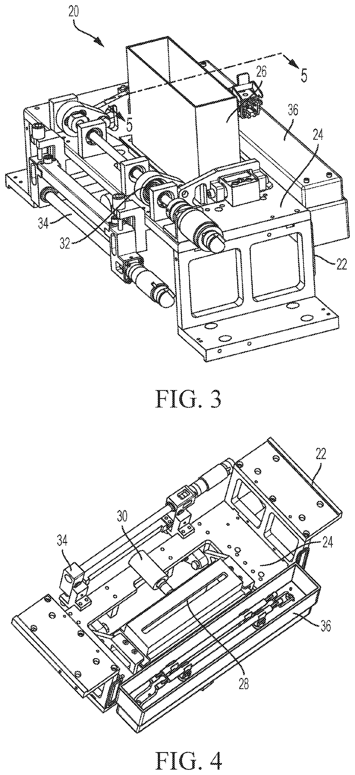
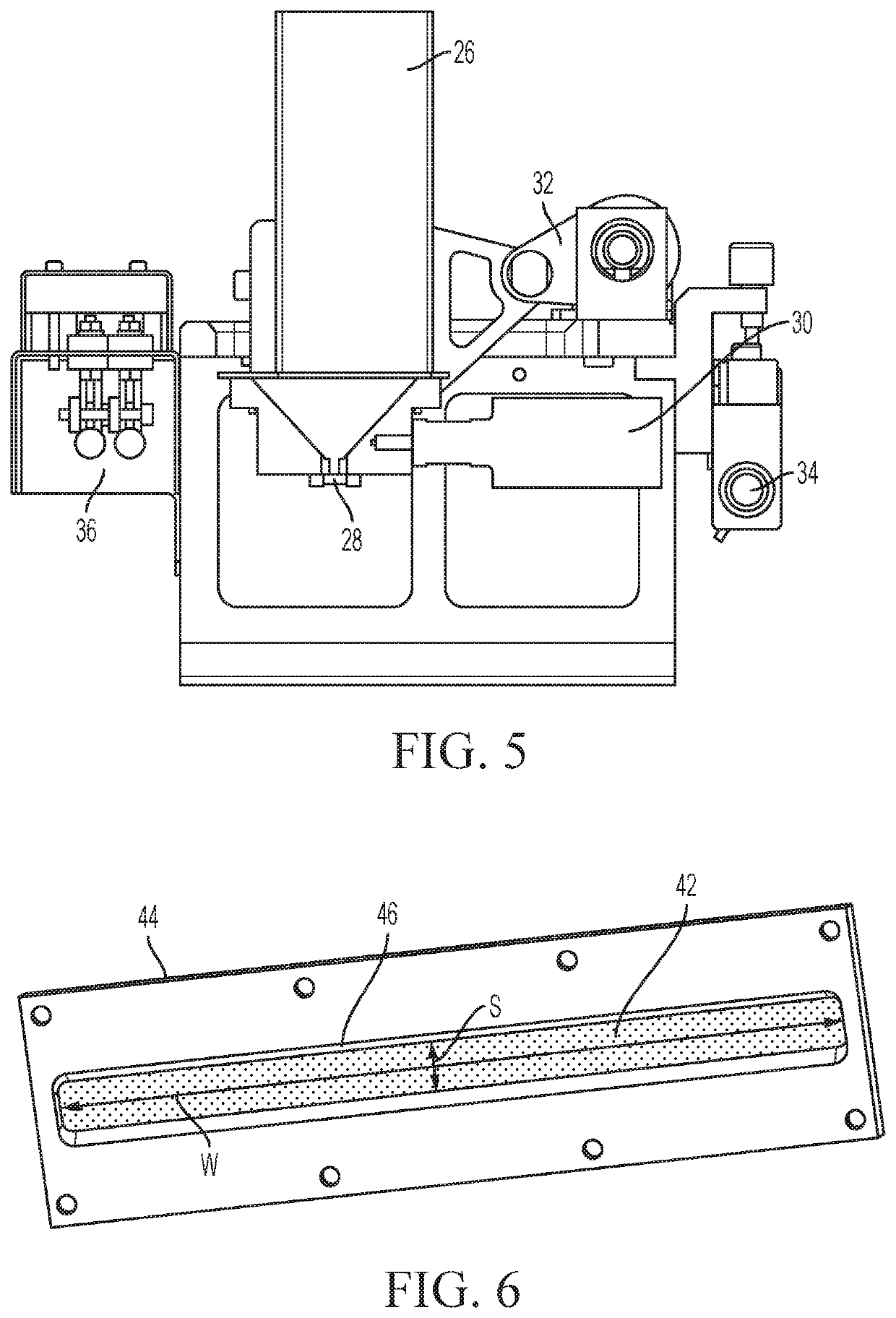
[0011]In at least some embodiments of the present invention, the recoaters of the powder-layer three-dimensional printers pelletize the build powder as the build powder is being dispensed onto a build bed. For ease of reference the resulting pellets are referred to hereinafter as “build powder pellets”. In these embodiments, the build powder pellets are formed by the application of ultrasonic vibrations to a sheet screen (as that term is defined below) as the build powder passes through and is pelletized by the sheet screen. This pelletization largely prevents the falling fine build powder of the build powder pellets from being caught in air (or other gas) currents during their fall to or impact with the build bed, thereby greatly reducing the amount of pluming normally associated with dispensing fine powders.
[0012]In at least some embodiments of the present invention, the recoaters of the powder-layer three-dimensional printer dispense the build powder more uniformly across and along the powder bed thus allowing for the use of less excess powder (as that term is defined below).
[0015]Some of the recoaters of the present invention provide a reduced minimum dispensing rate (as that term is defined below) required for reliable uniform coverage as compared to conventional recoaters. For example, some recoater embodiments permit 200% as an upper limit of the minimum dispersing rate as opposed to 400% or greater for some conventional recoaters. This allows for full build box depth builds without overflowing the collection chutes of or associated with the build box.
[0016]The modular design of preferred recoater embodiments allows for variations of the sheet screens to accommodate powders with different particle size distributions, densities, and flow characteristics.
[0017]Some embodiments of the present invention provide for localized dust collection around the perimeter of the build box. Collecting the dust at or near its source significantly reduces dispersion of fine particles within the machine work area, greatly reducing machine contamination.

Problems solved by technology

Two prevalent problems with the use of fine build powders are (a) the difficulty to create uniform layers over the entire print bed and (b) the propensity of the fine powders during deposition onto the build bed to “plume”, i.e. to be suspended in very slight drafts so as to be carried away by the drafts to other areas of the three-dimensional printer.
The former problem is present in all types of powder-layer three-dimensional printers, whereas the latter problem is not present or present in a diminished degree in those powder-layer three-dimensional printers in which the build area is maintained in a vacuum or near vacuum, e.g. electron beam melting three-dimensional printers.
Another problem inherent in forming the powder beds of powder-layer three-dimensional printer is the large amount of excess powder (as that term is defined later) that is needed to compensate for the lack of uniformity of powder dispensing across and along the powder bed.
The lack of uniformity and excess powder problems become amplified when fine powders are used because of the tendency to use thinner layers with decreased powder size.

Method used


Image

  • Improved Powder Distribution System for Three-Dimensional Printer
  • Improved Powder Distribution System for Three-Dimensional Printer
  • Improved Powder Distribution System for Three-Dimensional Printer

Examples


Embodiment Construction

[0056]Some preferred embodiments of the present invention are described in this section in detail sufficient for one skilled in the art to practice the present invention without undue experimentation. It is to be understood, however, that the fact that a limited number of preferred embodiments are described in this section does not in any way limit the scope of the present invention as set forth in the claims.

[0057]It is to be understood that whenever a range of values is described herein, i.e. whether in this section or any other part of this patent document, the range includes its end points and every point therebetween as if each and every such point had been expressly described. Unless otherwise stated, the words “about” and “substantially” as used herein are to be construed as meaning the normal measuring and / or fabrication limitations related to the value or condition which the word “about” or “substantially” modifies. Unless expressly stated otherwise, the term “embodiment” i...


PUM

PropertyMeasurementUnit
angleaaaaaaaaaa
angleaaaaaaaaaa
particle sizesaaaaaaaaaa

Abstract

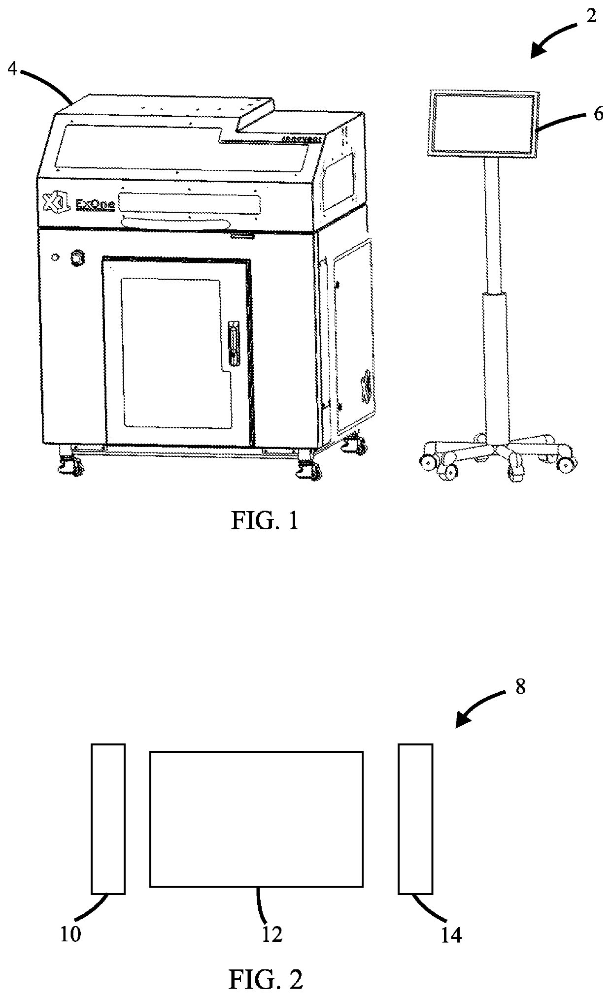
The present invention relates to apparatuses for distributing build powder in powder-layer three-dimensional printers (2) and for the collection of particulates of the build powder that have become suspended in the gaseous atmosphere in the vicinity of the build platform of the three-dimensional printer. These apparatuses include recoaters (20) that are particularly useful in providing uniform distribution of fine build powder across the width of the build platform or powder bed. The present invention also includes powder-layer three-dimensional printers (2) which comprise such apparatuses for distributing build powder and / or apparatuses for collecting such suspended particulates. The improved fine powder recoater (20) uses an ultrasonic transducer (30) to move powder through a sheet screen (28). The sheet screen (28) may be presented to the powder fed onto it in a narrow dispensing slot to limit the flow rate of powder from the dispenser and to provide control over the amount of powder dispensed. The width of the slot may extend to cover the entire build box fill zone. The ultrasonic transducer (30) is preferably adapted to periodically sweep through a range of frequencies during operation. The ultrasonic vibration system may be augmented with a low frequency vibration system. The dust collection system (160) draws air from the perimeter of the build box (172) down through the deck plate (170) of the printer (2) and out of the printer's housing (164) to an external dust collector (250).

Description

BACKGROUNDField of the Invention[0001]The present invention relates to powder-layer three-dimensional printers and methods of making articles thereby.Background of the Invention[0002]There are today various types of three-dimensional printers, i.e. devices that convert electronic representations of three-dimensional articles into the articles themselves by the systematic building-up of one or more materials. The apparatuses of the present invention find particular utility with the types of three-dimensional printers which create three-dimensional articles by selectively binding together preselected areas of successively deposited layers of powder. These types of three-dimensional printers are referred to herein as “powder-layer three-dimensional printers” because the construction of the three-dimensional article by such printers utilizes layers of powders as a build material. Examples of such types of powder-based three-dimensional printers include, without limitation, the binder-je...

Claims


Application Information

Patent Timeline
Patent Type & Authority Applications(United States)
IPC IPC(8): B29C64/329B29C64/205B07B1/40
CPCB29C64/205B07B1/40B33Y30/00B29C64/329B33Y10/00B22F3/004B22F2202/01B22F2999/00B33Y40/00B29C64/153B29C64/307B22F12/67B22F10/14B22F12/52B22F12/90B22F10/28Y02P10/25B22F10/10B29C64/255B29C64/209B29C64/35
Inventor VOSS, LAWRENCE JOSEPHBOLT, JOSEPH J.DUGAN, ANTHONY S.MCCOY, MICHAEL JOHNBRUNERMER, DANIEL T.INKS, TRAVIS MAXWELLKNOR, PAUL P.
Owner THE EX ONE
Learn More