Non-coupling two-dimension moving one-dimension turning three-freedom spatial parallel mechanism

A technology with a degree of freedom and no coupling, applied in manipulators, program-controlled manipulators, manufacturing tools, etc., can solve problems such as complex structures, and achieve broad application prospects and high practical value

Inactive Publication Date: 2008-03-19
HENAN UNIV OF SCI & TECH
View PDF3 Cites 18 Cited by
  • Summary
  • Abstract
  • Description
  • Claims
  • Application Information

AI Technical Summary

Problems solved by technology

Such as Patent No. 200410064955.X (name of invention: two-moving-one-rotating parallel mechanism for virtual-axis CNC machine tools and robots, application date: October 14, 2004, publication date: March 2, 2005, publication number: CN1156805A ), although the mechanism has partial decoupling, its structure is still relatively complex

Method used


Image

  • Non-coupling two-dimension moving one-dimension turning three-freedom spatial parallel mechanism

Examples


Embodiment 1

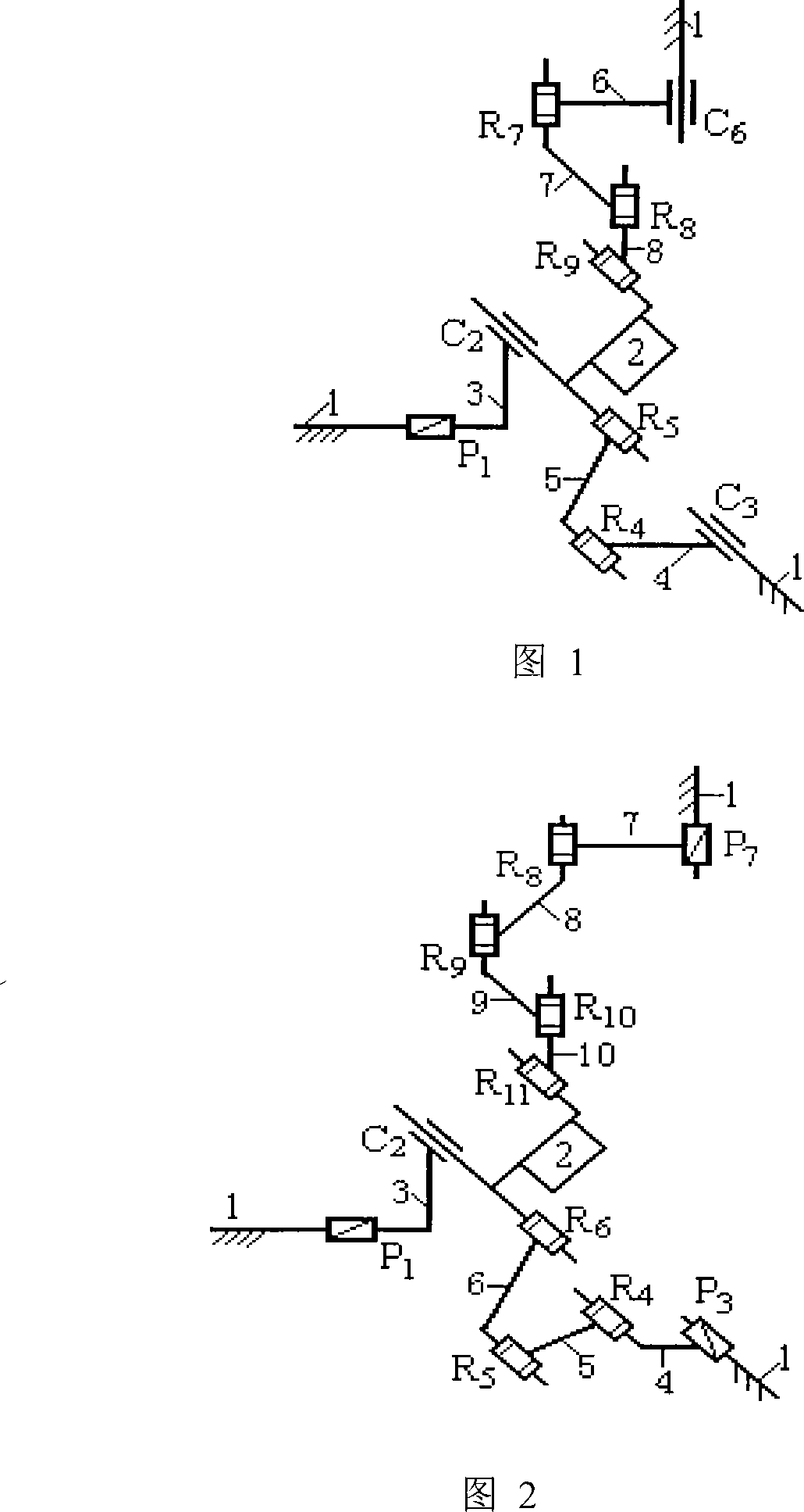
[0022] An uncoupled two-movement-rotation three-degree-of-freedom space parallel mechanism consists of a static platform 1, a dynamic platform 2, and three branches connecting the static platform 1 and the dynamic platform 2. Its specific structure is shown in Figure 1: the first Between the branch road from the static platform 1 to the moving platform 2 is a moving pair P 1 and one with the mobile vice P 1 Vertical Cylindrical Vice C 2 It is formed in series, and the two kinematic pairs are connected by component 3; the second branch is formed by a cylindrical pair C between the static platform 1 and the dynamic platform 2 3 and with this cylinder vice C 3 Two rotating pairs R with parallel axes 4 and R 5 The two adjacent kinematic pairs are connected in sequence through component 4 and component 5. The sequence and configuration relationship of the kinematic pairs from the static platform 1 to the dynamic platform 2 in this branch is C 3 / / R 4 / / R 5 ; The third branch...

Embodiment 2

[0025] A non-coupling two-movement-rotation three-degree-of-freedom space parallel mechanism consists of a static platform 1, a moving platform 2 and three branches connecting the two platforms. The specific structure is shown in Figure 2. Among them, the first branch is from the static platform 1 to the moving platform 2 by a mobile pair P 1 and one with the mobile vice P 1 Vertical Cylindrical Vice C 2 It is connected in series, and the two kinematic pairs are connected by a component 3; the second branch is from the static platform 1 to the moving platform 2 by a moving pair P 3 and three axes with which the moving pair P 3 Parallel rotary joint R 4 , R 5 and R 6It is formed in series, and the sequential kinematic pairs are connected by members 4, 5 and 6 respectively. The sequence and configuration relationship of the kinematic pairs from the static platform 1 to the dynamic platform 2 in this branch is P 3 / / R 4 / / R 5 / / R 6 ; The third branch is from the static p...


PUM


Abstract

A spatial parallel mechanism with no-coupling two translational one rotating tree- degree-of-freedom consists of a moving platform, a quiet platform and three bypasses connecting with the two platforms. Between the moving platform and the quite platform, the first bypass is connected in series with a moving pair and a cylindrical pair perpendicular to the moving pair; the first bypass connected in series with a cylindrical pair and two rotation pairs parallel to the axis of the cylindrical pair orderly and the third bypass is connected in series with a cylindrical pair two rotation pairs parallel to the axis of the cylindrical pair and a rotation pair vehicle to the axes of the two rotation pairs orderly; the three bypasses are respectively and pairwise perpendicular to the axis of the motion pair on the moving platform, thus forming spatial orthogonal structure; The axis of the cylindrical pair on the moving platform of the first bypass is coincident with the axis of the rotation pair on the moving platform of the second bypass, and is parallel to the axis of the rotating pair on the moving platform of the third bypass. By the control of the linear input of the driving pair on the quite platform, the two-dimensional movement and one- dimensional output on the moving platform can be realized.

Description

technical field [0001] The invention relates to an end effector of a robot, a machine tool, etc., in particular to a non-coupling two-movement-rotation three-degree-of-freedom space parallel mechanism that can be used for a parallel robot and a virtual-axis numerical control machine tool. Background technique [0002] The parallel mechanism generally consists of a moving platform, a fixed platform and 2-6 branches. Compared with the series mechanism, the parallel mechanism has the advantages of high rigidity, strong bearing capacity, high precision, and small self-weight-to-load ratio. Compared with the parallel mechanism with 6 degrees of freedom, the parallel mechanism with few degrees of freedom has the characteristics of simple structure, low cost, and relatively simple kinematics solution. Therefore, the parallel mechanism with few degrees of freedom has broad application prospects in industries such as industrial robots, virtual axis CNC parallel machine tools, coordi...

Claims


Application Information

Patent Timeline
Patent Type & Authority Applications(China)
IPC IPC(8): B25J19/00B25J9/08
Inventor 张彦斌吴鑫徐红玉何晓玲
Owner HENAN UNIV OF SCI & TECH
Why Eureka
Try Eureka