Eureka AIR delivers breakthrough ideas for toughest innovation challenges, trusted by R&D personnel around the world.

Tube grinder hollow shaft R area anti-fatigue performance designing method

A design method and anti-fatigue technology, which can be used in grinding machine parts, machine tools designed for grinding workpiece rotating surfaces, grinding/polishing equipment, etc., can solve problems such as unreasonable structural design of hollow shaft R area, and The effect of avoiding R zone fracture, good fatigue resistance and long service life

Inactive Publication Date: 2008-03-26
CITIC HEAVY INDUSTRIES CO LTD +1
View PDF0 Cites 0 Cited by
  • Summary
  • Abstract
  • Description
  • Claims
  • Application Information

AI Technical Summary

Problems solved by technology

[0004] In order to solve the unreasonable structural design of the R-zone of the hollow shaft, the present invention designs a design method for the anti-fatigue performance of the R-zone of the hollow shaft of the tube mill. The hollow shaft designed by this method has the advantages of simple structure, good fatigue resistance, and Long service life and other characteristics, better avoid the phenomenon of R zone fracture that often occurs in the hollow shaft

Method used


Image

  • Tube grinder hollow shaft R area anti-fatigue performance designing method

Examples


Embodiment Construction

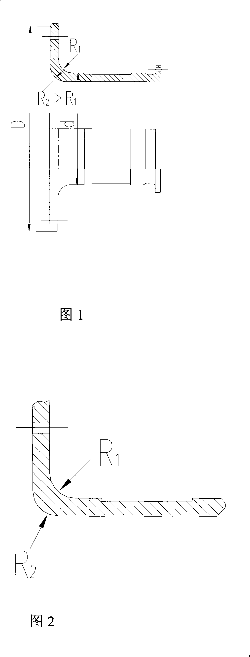
[0012] The design method of the anti-fatigue performance of the hollow shaft R zone of the tube mill of the present invention, wherein the R angle of the hollow shaft R zone is directly related to its stress concentration, that is, the inner circle R of the R zone 1 The larger the angle, the smaller the stress concentration; and the outer circle R of the R area 2 The greater the angle is, the thickness of the R zone becomes thinner. Under the same conditions, Figure 1 rotates along the axis of the hollow shaft compared with Figure 2, and the area of ​​rotation decreases by 23.3-38.5%, which reduces the fatigue strength of the hollow shaft. Therefore, the outer circle R 2 The suitable angle range is: 0.8R 1 ≤R 2 ≤R 1 .

[0013] The durability limit of the hollow shaft material is the direct basis for determining the strength of the hollow shaft under alternating stress. Therefore, improving the durability limit of the hollow shaft is very important for increasing the ability...


PUM


Abstract

The antifatigue design method for the R region of hollow shaft for tube mill is based on that the angle in the R region of hollow shaft is related directly with the stress concentration, i. e., increase in the inner circle R1 angle in the R region results in less stress concentration, and the increase excircle R2 angle or the decrease in the thickness in the R region results in small axis rotating area of the hollow shaft and low fatigue strength of the hollow shaft. Thus, the excircle R2 angle has the selection range of 0.8R1-R1. Thus designed hollow shaft has simple structure, high fatigue strength and long service life.

Description

technical field [0001] The invention belongs to the technical field of hollow shafts of tube mills, and in particular relates to a method for designing the anti-fatigue performance of the R zone of the hollow shafts of tube mills. Background technique [0002] The hollow shaft and the cylinder end cover together form the grinding head system of the tube mill. The hollow shaft is connected by the flange and the shaft shoulder section through the arc R area. The shaft shoulder belongs to the thin-walled round tube, as shown in Figure 1. The hollow shaft is supported on the bearing shell of the main bearing, bears the entire grinding body and the running dynamic load of the grinding body, and runs continuously under the action of alternating stress. It is the weakest link of the mill body and the most difficult part to control the manufacturing quality. . [0003] The damage of the hollow shaft below its material fatigue limit is caused by stress concentration and internal def...

Claims


Application Information

Patent Timeline
Patent Type & Authority Applications(China)
IPC IPC(8): B24B5/00B24B41/04
Inventor 刚梅林贺炎炎赵卫锋白洁
Owner CITIC HEAVY INDUSTRIES CO LTD
Why Eureka
Eureka Blog
Learn More