
Thickness changing sewing needle rod wire selecting mechanism

A sewing needle and thickness-changing technology, which is applied to the sewing machine thread take-up device, sewing machine components, sewing equipment, etc., can solve the problems of large needle stroke, poor stitch quality, and high labor intensity, and achieve moderate and balanced sewing thread tension. Appropriate tightness, neat and beautiful stitches

Inactive Publication Date: 2011-04-06
ZHEJIANG UNIV OF TECH
View PDF0 Cites 0 Cited by
  • Summary
  • Abstract
  • Description
  • Claims
  • Application Information

AI Technical Summary

Problems solved by technology

For example, the shoe mold feeds from left to right, and the amount of thread take-up changes from less to more. For ordinary sewing machines, the amount of thread take-up is the same, so it cannot be realized.
Sewing work with special requirements for complex thickness changes and large needle strokes can only be done by hand at present
However, manual sewing has low efficiency, poor stitch quality and high labor intensity.

Method used


Image

  • Thickness changing sewing needle rod wire selecting mechanism
  • Thickness changing sewing needle rod wire selecting mechanism
  • Thickness changing sewing needle rod wire selecting mechanism

Examples


Embodiment 1

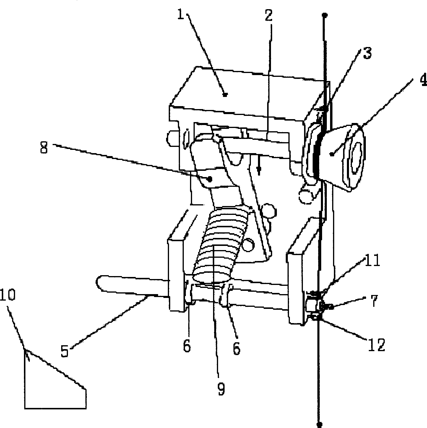
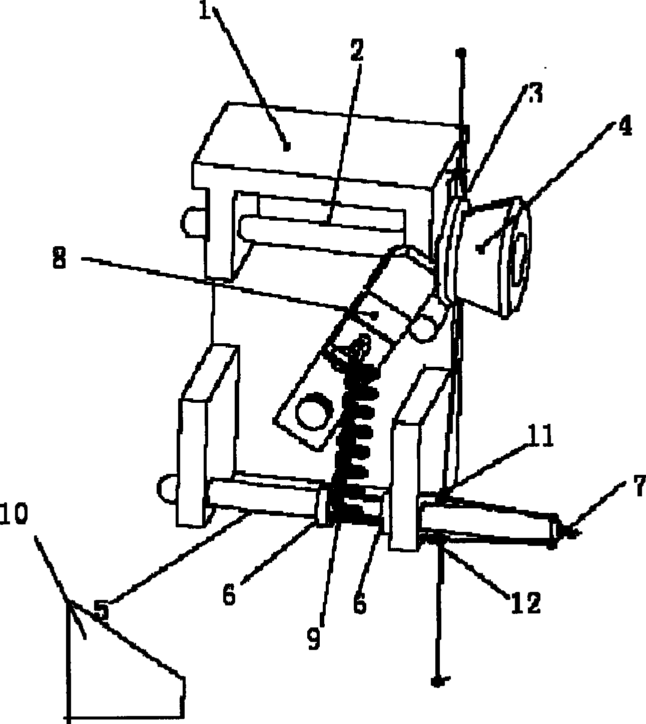
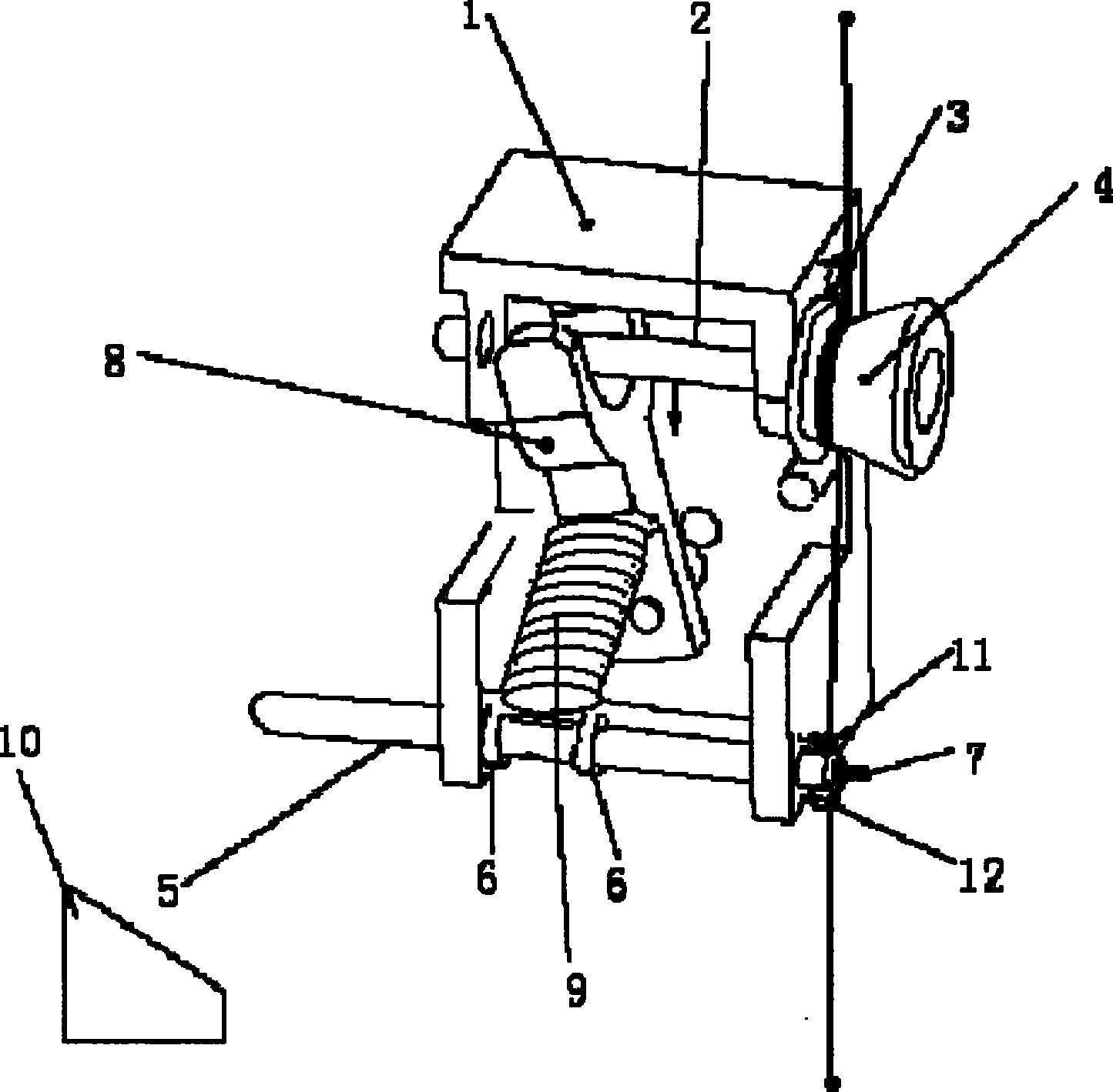
[0013] refer to figure 1 , figure 2 , a variable-thickness sewing needle bar thread take-up mechanism, including a mounting bracket 1, a horizontally arranged mounting shaft 2 is fixed on the mounting bracket 1, and a thread clamping gasket 3 and a thread clamping pad 3 are arranged on the mounting shaft 2 Nut 4 , the clamping washer 3 is slidably sleeved on the installation shaft 2 , and the clamping nut 4 is fixedly connected to the installation shaft 2 . Both the clamp spacer 3 and the clamp nut 4 are located on the outside of the mounting bracket 1, the clamp spacer 3 is located on the inside of the clamp nut 4, and the clamp spacer 3 and the clamp nut 4 to form a threading gap.

[0014] The mounting bracket 1 is pierced with a slide bar 5 that can slide horizontally, the slide bar 5 is located below the installation shaft 2, and the slide bar 5 between the two sides of the mounting bracket is provided with two stops. Sliding convex ring 6, the head of the slide bar 5 ...

Embodiment 2

[0019] refer to figure 1 , figure 2 The outer side of the mounting bracket is also provided with a second threading ring 11 and a third threading ring 12, the second threading ring 12, the third threading ring 13 and the threading ring 7 of the head of the slider are located at the On the same side of the mounting bracket 1 , the sliding bar 5 is located between the second threading ring 12 and the third threading ring 13 . This moment, the needle thread first walked around the threading slit, and then passed through the second threading ring 12, the threading ring 7, and the third threading ring 13 successively and drawn out. The rest of the structure and implementation are the same as in Embodiment 1.


PUM


Abstract

The thread take-up mechanism of thickness variable sewing needle bar includes one installation rack with one transverse installing shaft and one thread clamping spacer and one thread clamping nut to form one thread gap in between; one transversely sliding rod with two limiting rings and one thimble in the head; one shifting block hinged to the rack for shifting the thread clamping spacer and one tension spring to connect the shifting block to the sliding rod; and one wedge block to push the sliding rod to slide and fixed on the frame of sewing machine in the location corresponding to the lowest position of the sewing needle. The present invention completes the complicated mechanical operation of varying sewing thickness and increasing the needle stroke.

Description

(1) Technical field [0001] The invention relates to a sewing needle bar thread take-up mechanism, in particular to a sewing needle bar thread take-up mechanism with variable thickness. (2) Background technology [0002] In the past, sewing machines were mainly used in the garment industry, and the objects to be stitched were generally uniform with little change in thickness. But when the sewing object is shoe blanks, ordinary sewing equipment is no longer enough. It is not only irregular in shape, but also has a large variation in sewing thickness (when sewing the shoe blank, the sewing needle penetrates from the side of the shoe blank), which will inevitably lead to a difference in the amount of thread each time. For example, shoe molds are fed from left to right, and the amount of thread take-up varies from less to more. For ordinary sewing machines, the amount of thread take-up is the same, so it cannot be realized. Sewing work with special requirements for complex thic...

Claims


Application Information

Patent Timeline
Patent Type & Authority Patents(China)
IPC IPC(8): D05B49/00
Inventor 沈彦南刘红王惠李金国林康
Owner ZHEJIANG UNIV OF TECH
Learn More