Positioning structure of circuit board

A positioning structure and circuit board technology, applied in metal processing and other directions, can solve the problems of not meeting the requirements of mechanization, inability to disassemble at will, inconvenient picking and placing of materials, etc., to achieve improved efficiency, convenient positioning, and easy picking and placing of materials Effect

Active Publication Date: 2012-04-11
NETRON SOFT-TECH ZHUHAI CO LTD
View PDF7 Cites 9 Cited by
  • Summary
  • Abstract
  • Description
  • Claims
  • Application Information

AI Technical Summary

Problems solved by technology

[0003] At present, with the continuous development and growth of the electronic information industry, the demand for the output of flexible circuit boards is increasing, and the requirements for quality are becoming more and more stringent. Therefore, the requirements for punching machines for processing flexible circuit boards are also increasing. Before punching the circuit board, the punching position of the flexible board must be adjusted first, so that the alignment can be accurate when punching on the template, so the advance positioning of the circuit board is particularly important. The existing eight-hole circuit board positioning structure includes circuit Board and board, three positioning holes are symmetrically arranged on the two board sides in the length direction of the circuit board, and one positioning hole is respectively provided in the middle of the two board sides in the width direction of the circuit board. This structure has sufficient positioning accuracy, but the operation It is troublesome to look at. The tray and the fixed plate are also fixedly connected and cannot be disassembled at will. Less than the requirements of mechanization, which affects the production efficiency

Method used


Image

  • Positioning structure of circuit board
  • Positioning structure of circuit board
  • Positioning structure of circuit board

Examples


Embodiment Construction

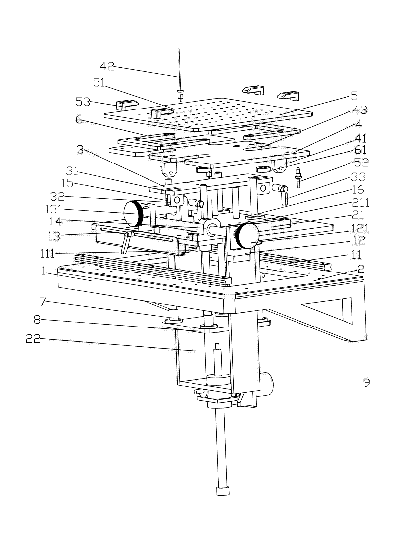
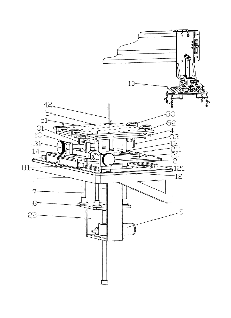
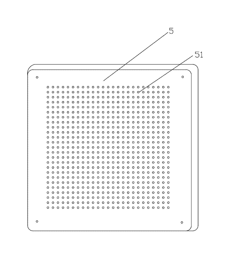
[0019] Such as Figure 1~Figure 3 As shown, a circuit board positioning structure, a circuit board positioning structure, including a base plate 1, a slide plate 2 fixed on the base plate 1, a guide rail 11 with a chute is installed on the base plate 1, and the bottom of the slide plate 2 A slide block 111 engaged with the guide rail 11 is fixed, so that the slide block 11 can drive the slide plate 2 to move in the guide rail 11, and a support 12 is fixed on the base plate 1, and a support for X is installed in the support 12. A fine-tuning screw 121 for direction adjustment, a support 13 is fixed on the slide plate 2, a fine-tuning screw 131 for adjusting the Y direction is installed in the support 13, and a fine-tuning screw 131 that matches the fine-tuning screw 121 is fixed on the slide 2. The threaded connector 14, the sliding sleeve 21 is fixed on the sliding plate 2, and the support plate 22 is connected to the bottom, and the sliding sleeve 21 is equipped with a moving...


PUM


Abstract

The invention discloses a positioning structure of a circuit board. The positioning structure comprises a base plate and a sliding plate which is fixedly arranged on the base plate, wherein a guide rail with a groove is arranged on the base plate; a bracket is fixedly arranged on the sliding plate; a sliding block which is occluded with the guide rail is fixedly arranged at the bottom of the sliding plate; a threaded connector matched with a fine-tuning screw is arranged on a movable plate; a support rod is arranged in the middle of the movable plate and a lining plate is connected onto the supporting rod; a fixing plate is arranged on the lining plate and is connected with a tray; and positioning holes which are arrayed according to a matrix are arranged at the top of the tray. Accordingto the positioning structure disclosed by the invention, the punching positions of a flexible circuit board can be positioned and punched in advance through a matrix positioning structure and an automatic-lifting system, and thus the processing with high precision and high efficiency is realized.

Description

technical field [0001] The invention relates to a circuit board positioning structure, in particular to a positioning structure used on a material table of a flexible circuit board punching machine. Background technique [0002] Flexible circuit board, referred to as soft board or FPC, is a highly reliable and excellent flexible printed circuit board made of polyimide or polyester film, with high wiring density and low weight. Light and thin. Mainly used in many products such as mobile phones, notebook computers, PDAs, digital cameras, and LCMs. [0003] At present, with the continuous development and growth of the electronic information industry, the demand for the output of flexible circuit boards is increasing, and the requirements for quality are becoming more and more stringent. Therefore, the requirements for punching machines for processing flexible circuit boards are also increasing. Before punching the circuit board, the punching position of the flexible board must...

Claims


Application Information

Patent Timeline
Patent Type & Authority Applications(China)
IPC IPC(8): B26D7/01
Inventor 刘惠民彭勇强
Owner NETRON SOFT-TECH ZHUHAI CO LTD
Why Eureka
Try Eureka