Massager
A technology of electric motor and changing mechanism, which is applied in the directions of kneading massage equipment, massage auxiliary products, physical therapy, etc., can solve the problems of inability to achieve massage massage and inability to adapt to massage machines.
- Summary
- Abstract
- Description
- Claims
- Application Information
AI Technical Summary
Problems solved by technology
Method used
Image

Examples
Embodiment Construction
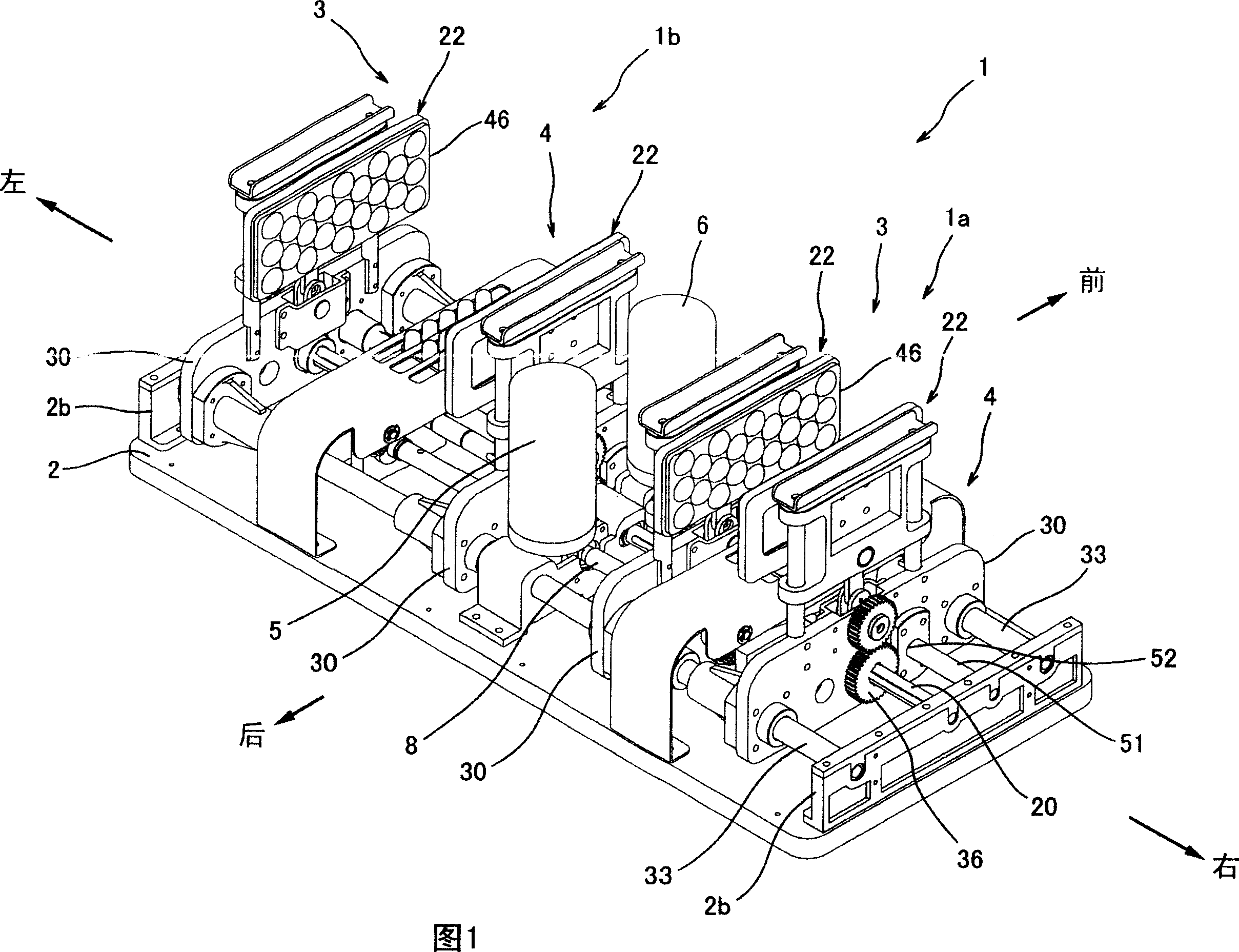
[0050] Hereinafter, a massage machine according to an embodiment of the present invention will be specifically described with reference to the drawings.
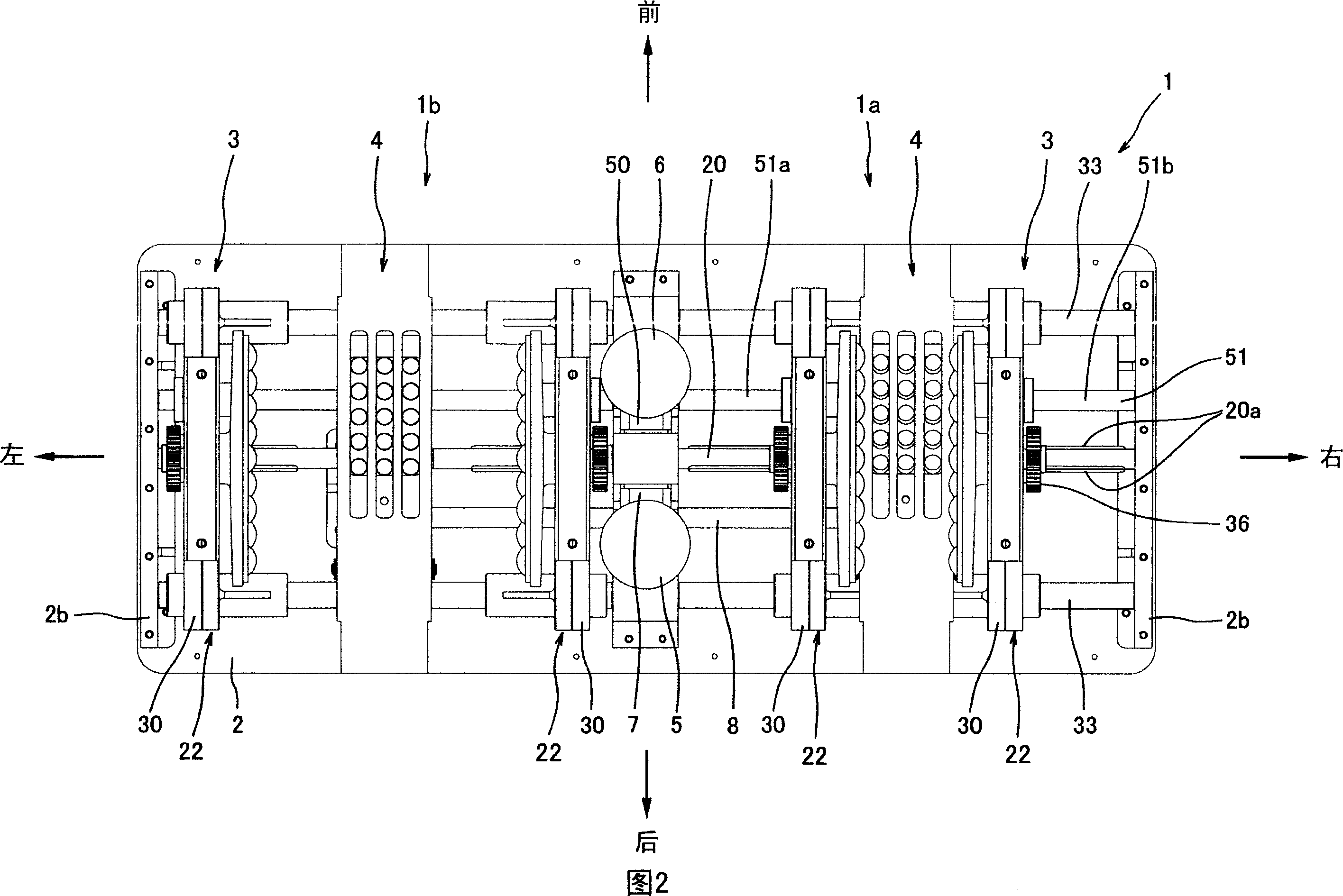
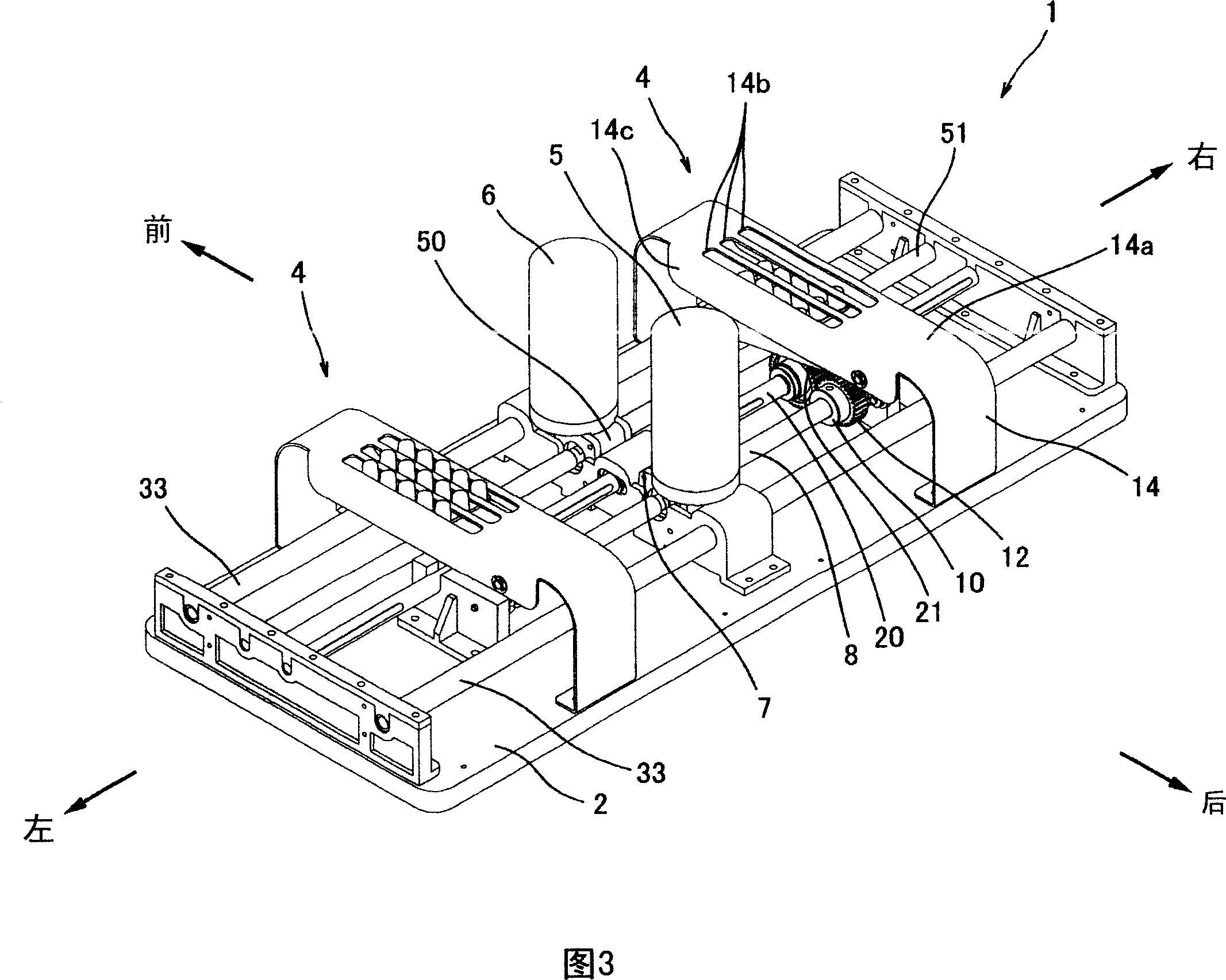
[0051] FIG. 1 is a perspective view showing an external configuration of a massage machine 1 , and FIG. 2 is a plan view of the massage machine shown in FIG. 1 . The massage machine 1 shown in FIG. 1 and FIG. 2 is mainly used for massaging body parts such as feet and arms of a person to be treated, and a cover for covering during use is omitted from the illustration.
[0052] As shown in FIG.1 and FIG.2, the massage machine 1 is equipped with the rectangular board|substrate 2 long in the left-right direction, and is equipped with the right side massage machine 1a and the left side massage machine 1b in the upper part. These massage machines 1a and 1b are equipped with a side massage unit (first massage unit) 3 which can rub and massage the body part of the person to be treated from the side, and a massage unit (first massage...
PUM
 Abstract
Description
Claims
Application Information
PatSnap Eureka turns technology decisions into work you can execute. Powered by our Innovation Knowledge Graph, it runs expert workflows across engineering, life sciences, materials and intellectual property. Get your review-ready output in minutes.


