DC magnetic-based position and orientation monitoring system for tracking medical instruments

a position and orientation monitoring and medical instrument technology, applied in the field of dc magnetic-based apparatus, can solve the problems of inability to meet all purposes, inability to meet the needs of one set of components or technologies, and inability to meet the needs of all purposes, etc., to achieve the effect of overcoming disposability and cost problems, and high volum

Active Publication Date: 2007-04-05
NORTHERN DIGITAL
View PDF15 Cites 192 Cited by
  • Summary
  • Abstract
  • Description
  • Claims
  • Application Information

AI Technical Summary

Benefits of technology

[0048] Yet another object of the present invention is to overcome the deficiencies of first-generation AC and second-generation DC magnetic systems employed in image-guided procedures. Most importantly, for 3D guidance in an image-guided procedure, the ferromagnetic issue must be addressed. Practical systems must perform robustly in the presence of these metals, commonly found in hospital operating rooms and surgical procedure tables. Third generation magnetic technology solves this problem by providing a padded planar transmitter, upon which the patient lays. It contains a permeable shield that prevents metal objects in the procedural table and beneath it from interfering with the fields generated above the patient. In addition to the ferrous metal issues, third-generation DC magnetic tracking presents a n...

Problems solved by technology

Because image-guided procedures are performed on different parts of the body and in varied operating rooms—filled with variable medical equipment that can severely distort and interfere electromagnetically with guidance measurements—no one set ...

Method used


Image

  • DC magnetic-based position and orientation monitoring system for tracking medical instruments
  • DC magnetic-based position and orientation monitoring system for tracking medical instruments
  • DC magnetic-based position and orientation monitoring system for tracking medical instruments

Examples


Embodiment Construction

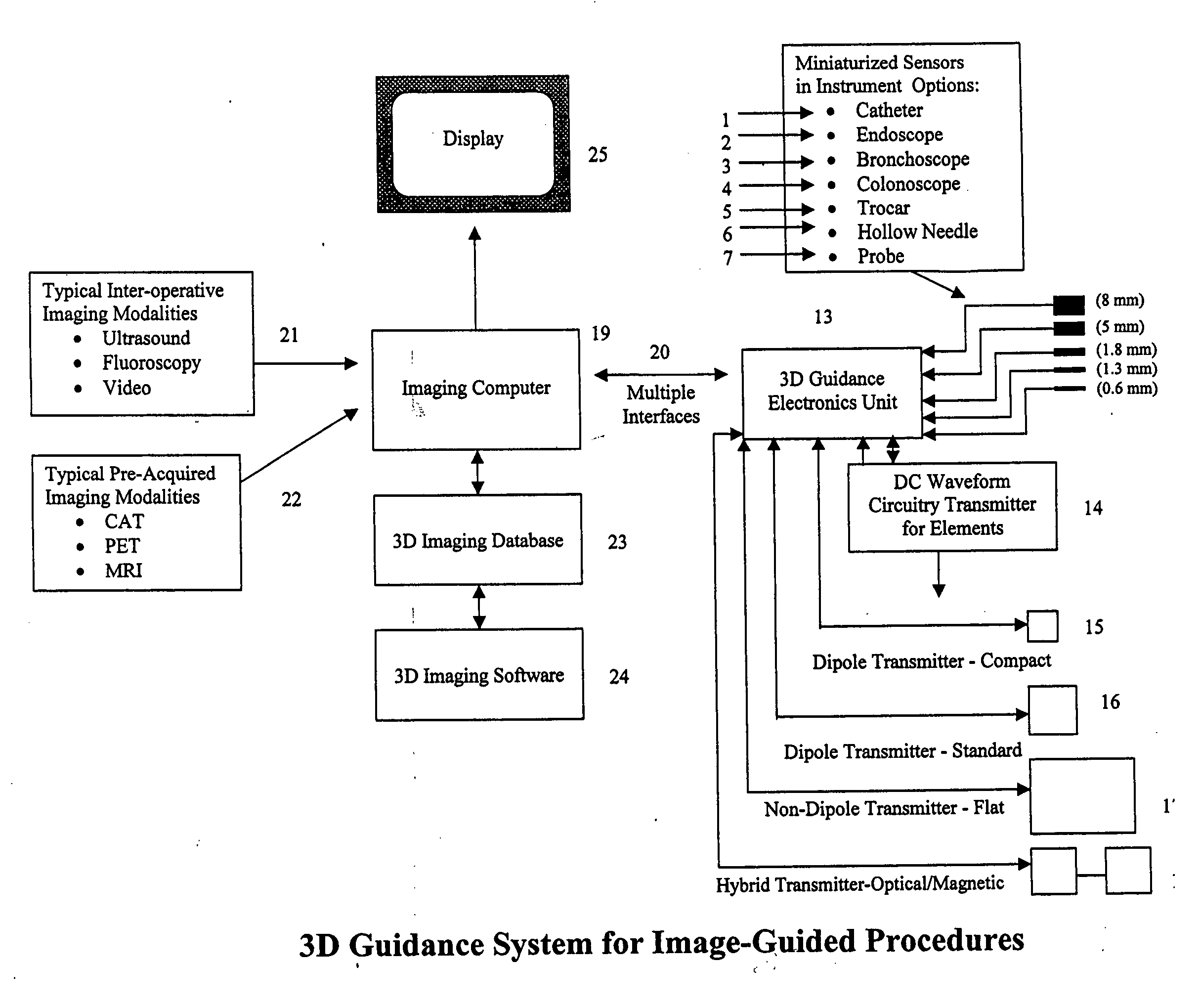
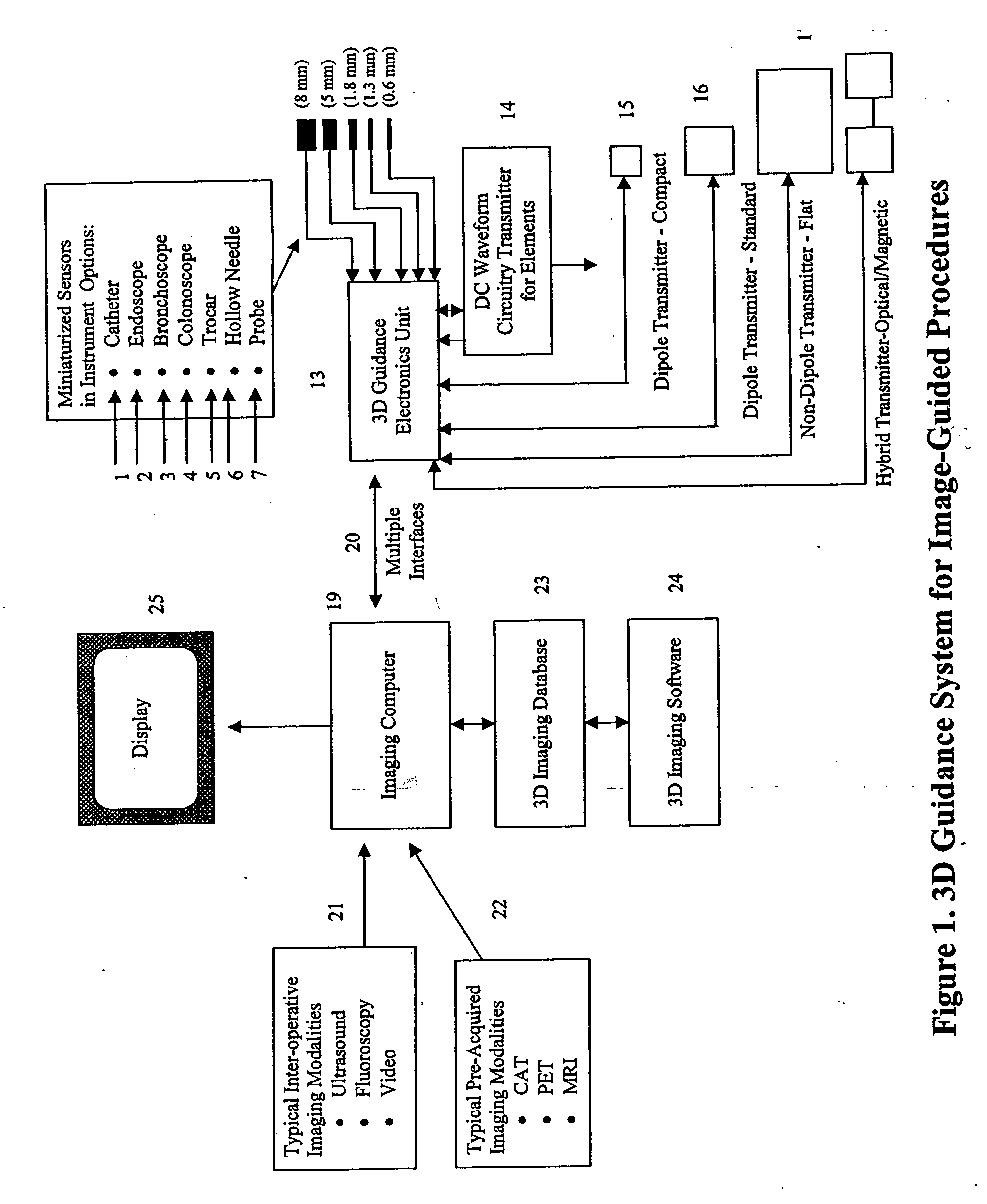
[0059]FIG. 1 presents an exemplary embodiment of the DC magnetic guidance system for image-guided medical procedures. A representative example of the DC tracking portion of the guidance system is detailed in U.S. Pat. No. 6,754,596 to Ashe, which is assigned to the assignee and incorporated herein by reference. The system includes a freely moving medical instrument, by which is meant all manner of surgical tools and devices for use in medical treatment. It is typically initialized for computer use as one or more of the devices, identified by the reference numerals 1, 2, 3, 4, 5, 6 or 7, namely, such as a catheter capable of being inserted within a patient's body through the skin, bodily orifice or incision. It permits targeting of an anatomical organ, structure or vessel for visualization, diagnostic and / or interventional purposes. Such instruments are typically thin, elongated and flexible, containing a proximal end for control by the physician and at the distal end, a DC sensor as...


PUM


Abstract

Miniaturized, five and six degrees-of-freedom magnetic sensors, responsive to pulsed DC magnetic fields waveforms generated by multiple transmitter options, provide an improved and cost-effective means of guiding medical instruments to targets inside the human body. The end result is achieved by integrating DC tracking, 3D reconstructions of pre-acquired patient scans and imaging software into a system enabling a physician to internally guide an instrument with real-time 3D vision for diagnostic and interventional purposes. The integration allows physicians to navigate within the human body by following 3D sensor tip locations superimposed on anatomical images reconstructed into 3D volumetric computer models. Sensor data can also be integrated with real-time imaging modalities, such as endoscopes, for intrabody navigation of instruments with instantaneous feedback through critical anatomy to locate and remove tissue. To meet stringent medical requirements, the system generates and senses pulsed DC magnetic fields embodied in an assemblage of miniaturized, disposable and reposable sensors functional with both dipole and co-planar transmitters.

Description

BACKGROUND OF THE INVENTION [0001] The present invention relates to a DC magnetic-based apparatus and means to detect—even in the presence of conductive and ferrous metals as well as stray electromagnetic fields—the three-dimensional location of medical instruments within the human body and use this information for guidance purposes in image-guided procedures. [0002] It provides an optimal means of performing electromagnetic guidance within image-guided medical procedures. Based on the principles of pulsed DC magnetic tracking, a panoply of sensors and transmitters is provided to address the requirements of myriad interventional and diagnostic procedures. Procedural requirements commonly include tracking above a metal bed, tracking a catheter inside a patient, and even hybrid tracking methods for localizing miniaturized sensors over the full length of a human body. Once optimal components are selected, system parameters are optimized. These parameters, which directly affect the accu...

Claims


Application Information

Patent Timeline
IPC IPC(8): A61B5/00
CPCA61B5/06A61B5/062
Inventor SCULLY, JACK T.SCHNEIDER, MARK R.
Owner NORTHERN DIGITAL
Why Eureka
Try Eureka