
Drive for a conveyor, in particular a baggage conveyor at an airport facility

A driving device and conveyor technology, which is applied in the direction of conveyors, transportation and packaging, etc., can solve the problems of large extrusion force, wear, and increased deflection radius of the transmission belt, and achieve the advantages of avoiding wear, low price, and simplified drive unit Effect

Inactive Publication Date: 2008-04-02
SIEMENS AG
View PDF1 Cites 3 Cited by
  • Summary
  • Abstract
  • Description
  • Claims
  • Application Information

AI Technical Summary

Problems solved by technology

[0004] Drive belts constructed as rubber-flat belts have the disadvantage that, due to the start and stop of the conveyor, a high compressive force must be provided, which is amplified by the narrow deflection radius of the drive belt
The result is very high wear, especially the slipping of drive belts is always unavoidable

Method used


Image

  • Drive for a conveyor, in particular a baggage conveyor at an airport facility

Examples


Embodiment Construction

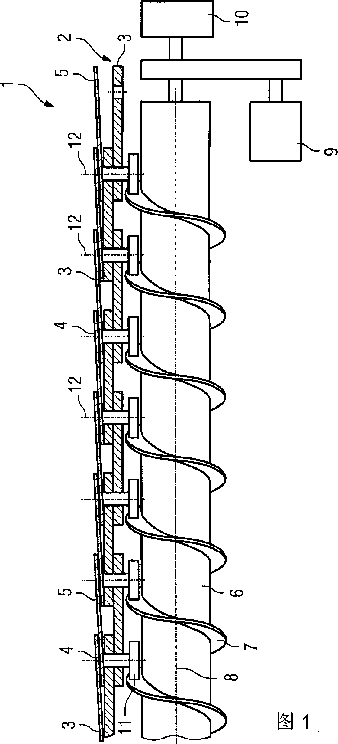
[0018] The drive of the baggage conveyor is designated overall with 1 . Designated overall at 2 is a traction chain consisting of individual chain links 3 which are connected to each other by means of joint bolts 4 . The swing bolt 4 allows the deflection of the drag chain in a horizontal plane, ie perpendicular to the plane shown. Plate-shaped brackets, shown schematically at 5 , are attached to the traction chain 2 , which overlap each other and provide a scale-like support surface for aircraft luggage (not shown) lying flat thereon.

[0019] The vertically oriented swing bolt 4 extends downwards and serves as a support for a driver which is designed as a roller 6 and is mounted coaxially for rotation about the longitudinal axis 12 of the swing bolt 4 . Arranged below the traction chain 2 is a helically toothed worm 6 according to the invention, the longitudinal axis 8 of which extends parallel to the direction of movement of the traction chain 2 . The worm is designed as ...


PUM


Abstract

The present invention relates to a drive for a conveyor in particular for a baggage conveyor, which is provided with flat shape brackets (5) overlap jointed with each other and fixed on a continuous rounding and articulated guide chain (2). In order to construct the drive in simply, effective and high effective way, the drive is provided with at least one rotatably driven worm (6) with spiral shape teeth parallel to the conveying direction. The worm is cooperated with a follower (11) which is embedded in the tooth part (7) of the worm (6) and arranged on the guide chain (2) in a way of worm gear worm wheel when the worm is driven to rotate around the longitudinal axis (8).

Description

technical field [0001] The invention relates to a drive for conveyors, especially baggage conveyors in airport installations, wherein a plurality of overlapping plate-shaped carriages are guided on a continuous running track for transporting Items of luggage on the carrier, and the carrier is secured to an articulated traction chain that also circulates continuously in the running track, wherein the traction chain can be deflected in at least one plane about the hinged bolt and can pass the position It is driven by a fixed drive mechanism, which acts on the rectilinear section of the traction chain, which is composed of a plurality of chain links, so that the traction chain advances in the transport direction. Background technique [0002] Conveyors of the type mentioned at the outset are mostly used in public areas of airport installations, as well as in non-public areas, and are used there, for example, to transport luggage. Baggage conveyors of this type are known above ...

Claims


Application Information

Patent Timeline
Patent Type & Authority Applications(China)
IPC IPC(8): B65G23/20B65G17/06
CPCB65G23/20B65G2201/0264B65G17/065
Inventor T·赫尔格特
Owner SIEMENS AG
Learn More