LED bulb socket

An LED bulb holder, LED bulb technology, applied in lighting devices, light sources, components of lighting devices, etc., can solve the problems of high production cost and low market acceptance, and achieve low cost, high market acceptance, and improved lighting. effect of effect

Inactive Publication Date: 2008-04-02
ADVANCED THERMAL DEVICES
View PDF0 Cites 6 Cited by
  • Summary
  • Abstract
  • Description
  • Claims
  • Application Information

AI Technical Summary

Problems solved by technology

However, this method of installing light-transmitting lenses for each LED bulb one by one has high production costs and low market acceptance.

Method used


Image

  • LED bulb socket
  • LED bulb socket

Examples


Embodiment Construction

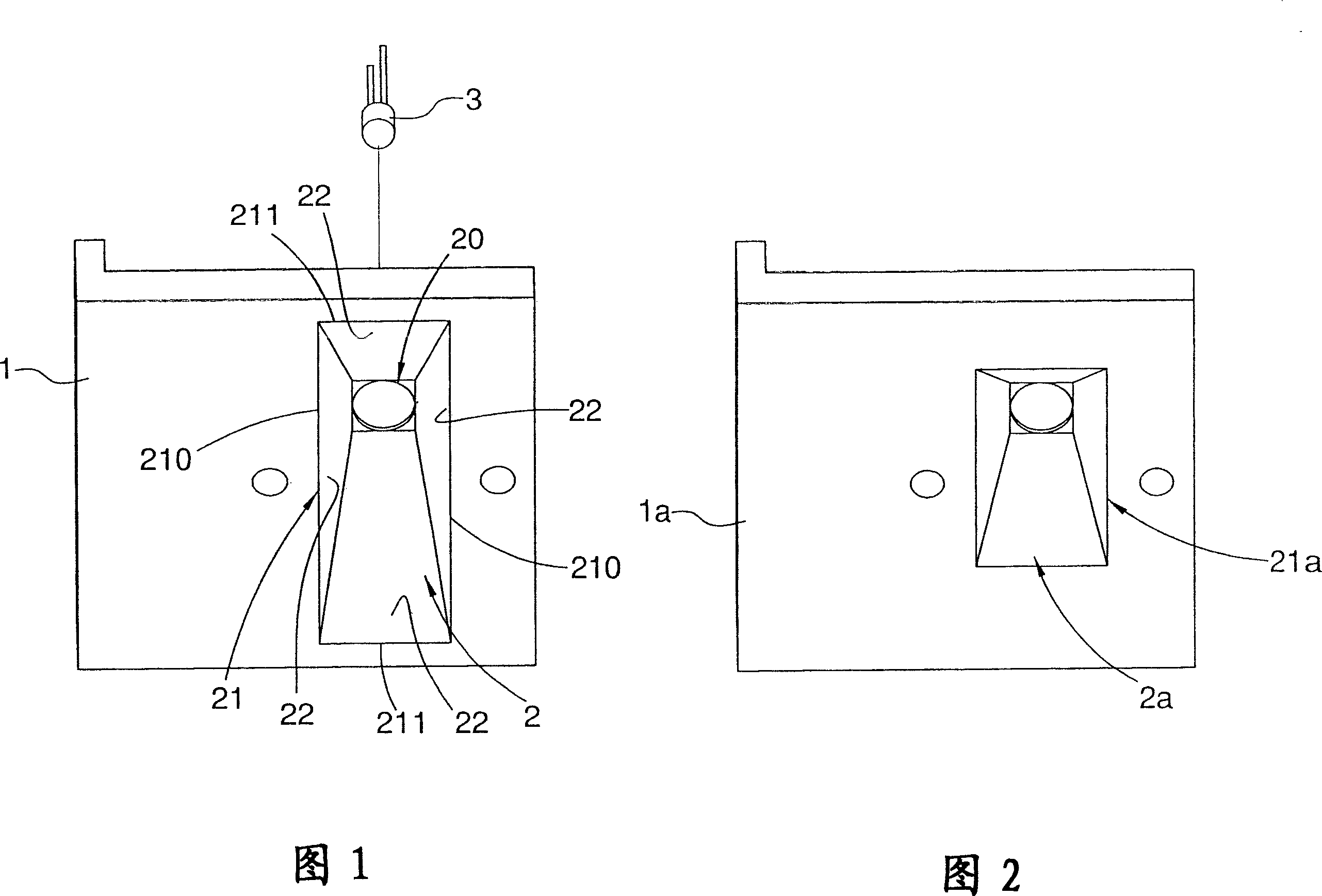
[0021] As shown in Figure 1, an LED bulb socket 1 of the present invention has a bulb hole 2, and the bulb hole 2 has a mounting opening 20 for installing an LED bulb 3, and a light emitting port 21 is larger than and facing the The installation opening 20 , a light reflecting surface 22 gradually extends from the periphery of the installation opening 20 to the periphery of the light emitting opening 21 .

[0022] Since the periphery of the light exit 21 includes two opposite long sides 210 and two opposite short sides 211, and the light reflective surface 22 gradually extends from the periphery of the installation port 20 to the periphery of the light exit 21, so the The light reflecting surface 22 is not conical. This feature will cause the light emitted by the LED bulb 3 and reflected by the light reflecting surface 22 to exit the light exit 21 in an asymmetric distribution, which is used to solve the problem that the reflected light caused by the known conical light reflec...


PUM


Abstract

The invention provides a LED bulb base.the LED buld base comprises a bulb hole provided with a mounting hole inside which a LED bulb is arranged, a light outlet rightly facing with the mounting hole is larger in diameter than the mounting hole, a light reflection surface is gradually extended from the periphery of the mounting hole to the periphery of the light outlet; the periphery of the light outlet is provided with two relatively long edges and two relatively short edges. Key points of the LED bulb base is that the light reflection surface is not cone-shaped, lights reflected out by the light reflection surface are asymmetrically distributed in order to strengthen the illuminating effect.

Description

technical field [0001] The invention relates to the technology of lighting equipment, especially related to the light reflection surface of the LED bulb holder. Background technique [0002] In China Taiwan Publication No. I255321 Patent Invention Case, a conical LED bulb hole is disclosed for forming a conical light reflection surface. This kind of conical LED bulb hole is quite common, and the LED bulb installed in the LED bulb hole can project a conical light beam from the light reflecting surface with the same shape as the LED bulb hole. The light of this beam is symmetrically distributed, which is not conducive to road lighting, and the loss is high. Therefore, it is also used to place a special light-transmitting lens in front of each LED bulb, so that the emitted light is distributed asymmetrically, so as to solve the aforementioned problems. However, the method of installing light-transmitting lenses for each LED light bulb one by one has high production costs and ...

Claims


Application Information

Patent Timeline
Patent Type & Authority Applications(China)
IPC IPC(8): F21V7/04F21V21/00F21Y101/02F21Y115/10
Inventor 黄秉钧黄焕翔叶裕源
Owner ADVANCED THERMAL DEVICES
Why Eureka
Try Eureka