Projection device and color wheel module used for the same

A projection device and color wheel technology, applied in projection devices, optics, instruments, etc., can solve problems such as noise and vibration

Inactive Publication Date: 2008-04-02
DELTA ELECTRONICS INC
View PDF0 Cites 7 Cited by
  • Summary
  • Abstract
  • Description
  • Claims
  • Application Information

AI Technical Summary

Problems solved by technology

Under such high-speed operation, the known color wheel adopts a single-direction fixed structure with a fixed frame, which will generate considerable noise and vibration, thus becoming the main source of noise and vibration for DLP projection devices.

Method used


Image

  • Projection device and color wheel module used for the same
  • Projection device and color wheel module used for the same

Examples


Embodiment Construction

[0025] Since the feature of the present invention focuses on the technology of fixing the color wheel module, the following description only focuses on the color wheel module and its surrounding main components in the projection device, and the rest of the components that are not directly related to the color wheel module will not be described here. .

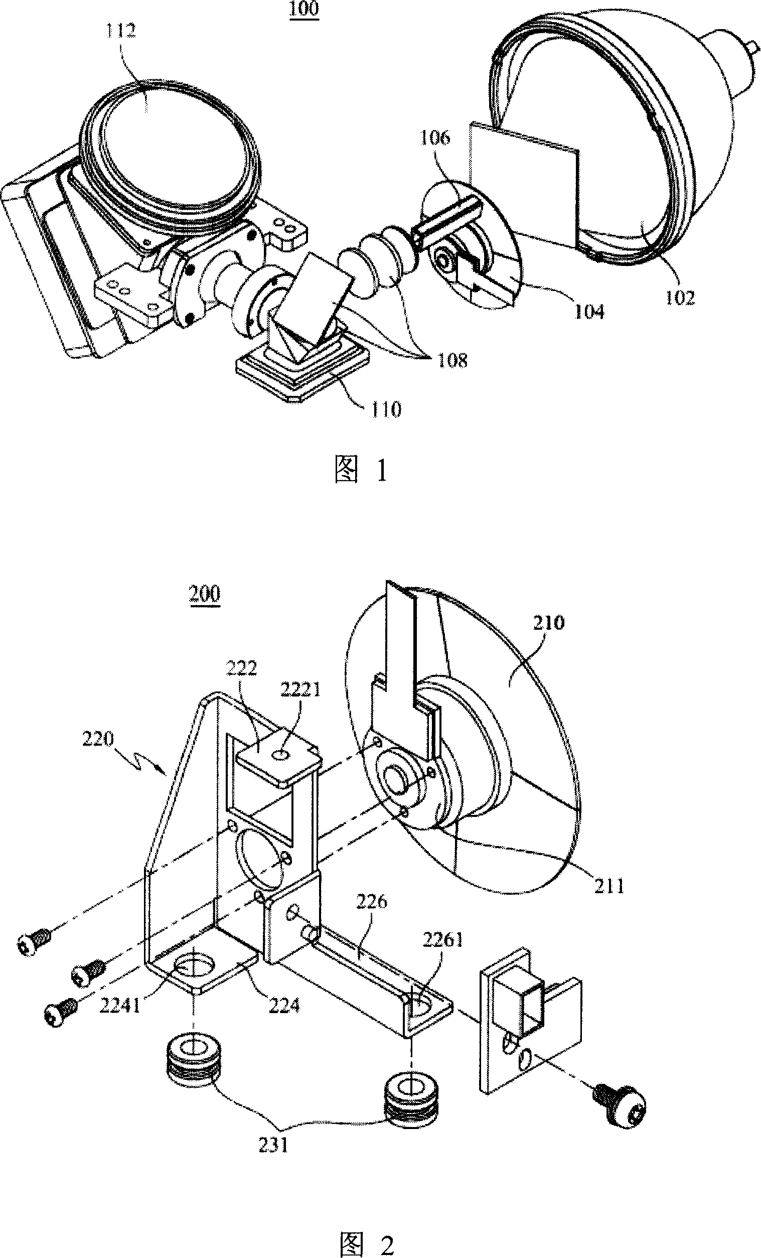
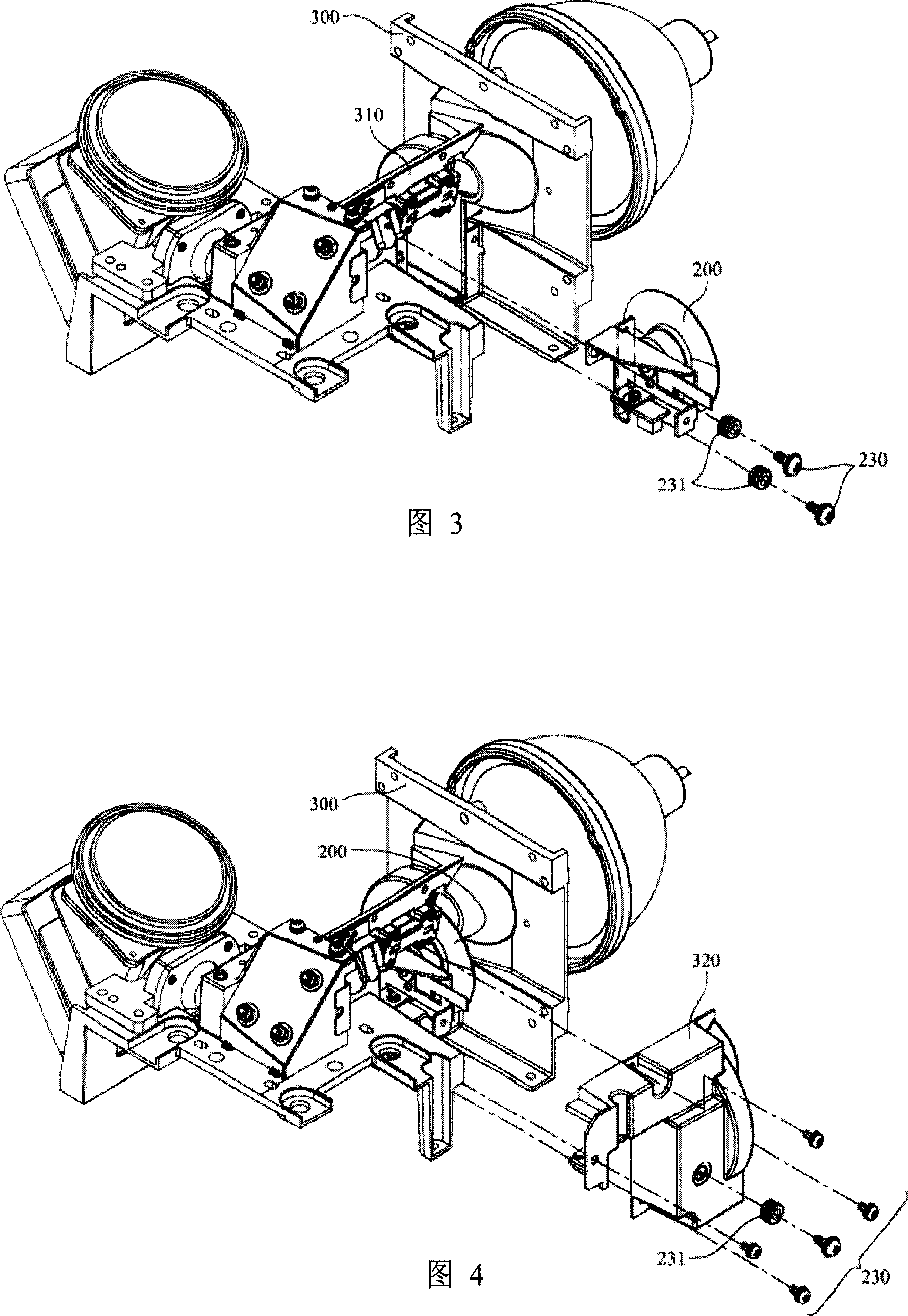
[0026] Please refer to FIG. 2 and FIG. 3 together, wherein FIG. 2 is a schematic diagram of the color wheel module 200 in an embodiment of the present invention, and FIG. 3 shows the internal light of the color wheel module 200 and the projection device (not shown in the figure). A combined schematic diagram of the machine 300. In a preferred embodiment, the color wheel module 200 includes a color wheel 210 , a support frame 220 and a connecting device. The color wheel 210 is connected with the support frame 220 to form the main structure of the color wheel module. Secondly, the supporting frame 220 includes a first fixing ba...


PUM


Abstract

The invention provides a projecting apparatus and a color wheel module used in the projecting apparatus, wherein, the projecting apparatus comprises a bare engine and a color wheel module which comprises a color wheel, a connecting device and a support frame, wherein, the color wheel is connected with the support frame which comprises a first permanent seat and a second permanent seat; the first permanent seat and the second permanent seat are connected to the bare machine through the connecting device, and the first permanent seat, relative to the center of the color wheel, is arranged opposite to the second permanent seat positively or obliquely with a certain angle.

Description

technical field [0001] The invention relates to a color wheel module used in a projection device and the projection device, in particular to a module design for stably fixing the color wheel module on the projection device. Background technique [0002] Currently, digital light processing (DLP) technology is commonly used in digital projection devices as a method for generating digital images. This technology is mainly developed based on the Micro Electro Mechanical System (MEMS) of the Digital Micromirror Device (DMD) and other peripheral optical components. Please refer to FIG. 1 , which shows an exploded view of main components of a conventional DLP projection device 100 . The DLP projection device 100 includes a light source 102 , a color wheel 104 , a light guide 106 , a lens set 108 , a DMD 110 , and a projection lens 112 . Wherein, according to the forward direction of light, the entire projection device 100 can be divided into two major systems, one is the light so...

Claims


Application Information

Patent Timeline
Patent Type & Authority Applications(China)
IPC IPC(8): G03B21/14G03B21/00
Inventor 吕昌兴张明宗
Owner DELTA ELECTRONICS INC
Why Eureka
Try Eureka