Supercharge Your Innovation With Domain-Expert AI Agents!

Electric power supply system with remote control circuit and its operating method

A technology of remote control and power supply system, applied in circuit devices, battery circuit devices, current collectors, etc., can solve the problem that the output voltage of the traditional power supply 101 cannot be changed, the volume of the traditional power supply 101 cannot be flexibly designed, parallel power supply, etc. question

Active Publication Date: 2008-04-02
COMPAL ELECTRONICS INC
View PDF0 Cites 2 Cited by
  • Summary
  • Abstract
  • Description
  • Claims
  • Application Information

AI Technical Summary

Problems solved by technology

[0004] In the prior art shown in FIG. 1 , since the voltages of the traditional power supply 101 and the battery 105 cannot be adjusted to be consistent, the traditional power supply 101 and the battery 105 cannot supply power to the system 106 at the same time.
If the load of the system 106 is increased to 50W, the battery 105 cannot supply power to the system in parallel, because the second switch 104 through which the current I flows is a general P-type metal oxide semiconductor transistor (P) that includes a body diode (body diode). -type metal-oxide-semiconductortransistor, referred to as PMOS) as an isolation switch, so as to control the power supply of the battery 105, when the traditional power supply 101 takes a protective action (for example, when the rated output power of the traditional power supply 101 is exceeded) or the traditional power supply When 101 does not exist, the second switch 104 will be in the conduction (on) state, and when the load of the system 106 increases, the general PMOS containing the body diode cannot effectively rectify, so it will cause the second switch 104 to burn out, thus As a result, the battery 105 and the traditional power supply 101 cannot supply power to the system 106 at the same time
[0005] In addition, since this prior art cannot change the output voltage of the conventional power supply 101, the output voltage cannot be changed in the range of 9-13 volts to approach the output voltage of the battery 105, so It also cannot meet the requirements of the concept of the Narrow Direct Current Voltage 2 (Narrow Direct Current Voltage 2, also known as Narrow VDC2 or NVDC2) proposal introduced by Intel (Intel), and because the system power supply 101 needs to provide at least the system 106 However, the traditional power supply 101 cannot be powered by other power sources in parallel, so the volume of the traditional power supply 101 cannot be flexibly designed

Method used


Image

  • Electric power supply system with remote control circuit and its operating method
  • Electric power supply system with remote control circuit and its operating method
  • Electric power supply system with remote control circuit and its operating method

Examples


Embodiment Construction

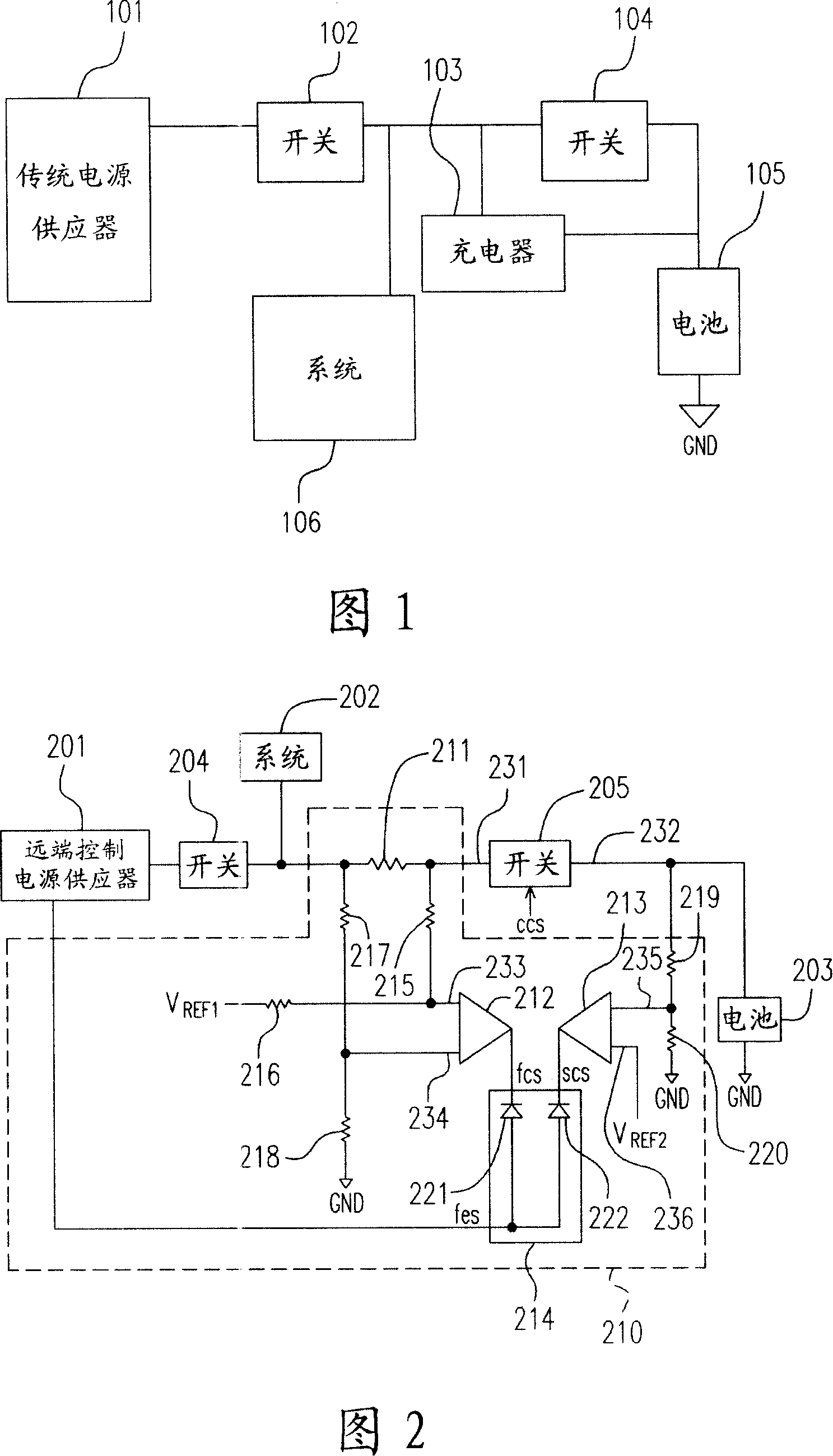
[0057] FIG. 2 is a circuit block diagram of a power supply system with a remote control circuit according to a preferred embodiment of the present invention. It includes a remote control power supply 201 , a system 202 , a battery 203 , a first switch 204 , a second switch 205 , and a remote control circuit 210 . The remote control circuit 210 includes a first resistor 211, a first operational amplifier 212, a second operational amplifier 213, a selection circuit 214, a second resistor 215, a third resistor 216, a fourth resistor 217, a fifth resistor 218, a sixth resistor 219, and the seventh resistor 220.

[0058] Wherein, the first terminal 231 of the second switch 205 is coupled to the system 202 through the first resistor 211, and the first terminal 231 of the second switch 205 is also coupled to the remote terminal of the first switch 204 through the first resistor 211 in turn. The power supply 201 is controlled, and the second terminal 232 of the second switch 205 is c...


PUM


Abstract

The invention relates to a remote control circuit power supply system and a power supply system operation method. The power supply system takes the advantage of the remote control power supply and the battery to supply power to the system, and the remote control circuit, and the remote control circuit comprises a first resistance, a first operational amplifier, a second operational amplifier, and an option circuit. The first resistance is coupled between the remote control power and the battery; the first operational amplifier detests the current of the first resistance to output a first control signal; the second operational amplifier detects the voltage of the battery to output a second control signal. The one with lower voltage in the first control signal and the second control signal output by the circuit is chosen to be the remote control signal for adjusting the remote the voltage of the remote control power supply, which makes the voltage of the remote control power supply and that of the battery close to each other.

Description

technical field [0001] The present invention relates to a power supply system and a power supply system operation method, and in particular to a power supply system with a remote control circuit and a power supply system operation method capable of simultaneously supplying power to the system by a power supply and a battery . Background technique [0002] Today's electronic products are very particular about the stability of the power source, because if the power supply of the electronic product is unstable, it will directly affect the stability and reliability of the electronic product. Therefore, one technique is to use a power supply and a battery to supply power required by electronic products, as shown in FIG. 1 . [0003] FIG. 1 is a schematic diagram of an existing power supply system. Please refer to FIG. 1 . FIG. 1 includes a conventional power supply 101 , a first switch 102 , a charger 103 , a second switch 104 , a battery 105 , and a system 106 . Wherein, it i...

Claims


Application Information

Patent Timeline
IPC IPC(8): H02J7/34
Inventor 庄志堂吕世钦
Owner COMPAL ELECTRONICS INC
Features
  • R&D
  • Intellectual Property
  • Life Sciences
  • Materials
  • Tech Scout
  • Unparalleled Data Quality
  • Higher Quality Content
  • 60% Fewer Hallucinations
Learn More