
Image pickup device

A camera device, camera technology, applied in the direction of image communication, TV, transducer shell/cabinet/stand, etc., can solve the problem of difficult sound with a sense of depth and so on

Inactive Publication Date: 2008-04-02
SONY GRP CORP
View PDF1 Cites 6 Cited by
  • Summary
  • Abstract
  • Description
  • Claims
  • Application Information

AI Technical Summary

Problems solved by technology

[0006] (2) Since the pair of microphone mechanisms 105 are arranged in the lateral direction and assembled in the above-mentioned concave portion 103, although it is effective for capturing the sound from the front, it is difficult to give the sound a sense of depth.

Method used


Image

  • Image pickup device
  • Image pickup device
  • Image pickup device

Examples


Embodiment Construction

[0032] Hereinafter, the present invention will be described in the order of (1) the schematic structure of the imaging device, (2) the structure of the microphone mechanism, (3) the structure of the grip part (fingertip contact part), (4) the function, and (5) other embodiments. Invented camera.

[0033] (1) Outline structure of imaging device

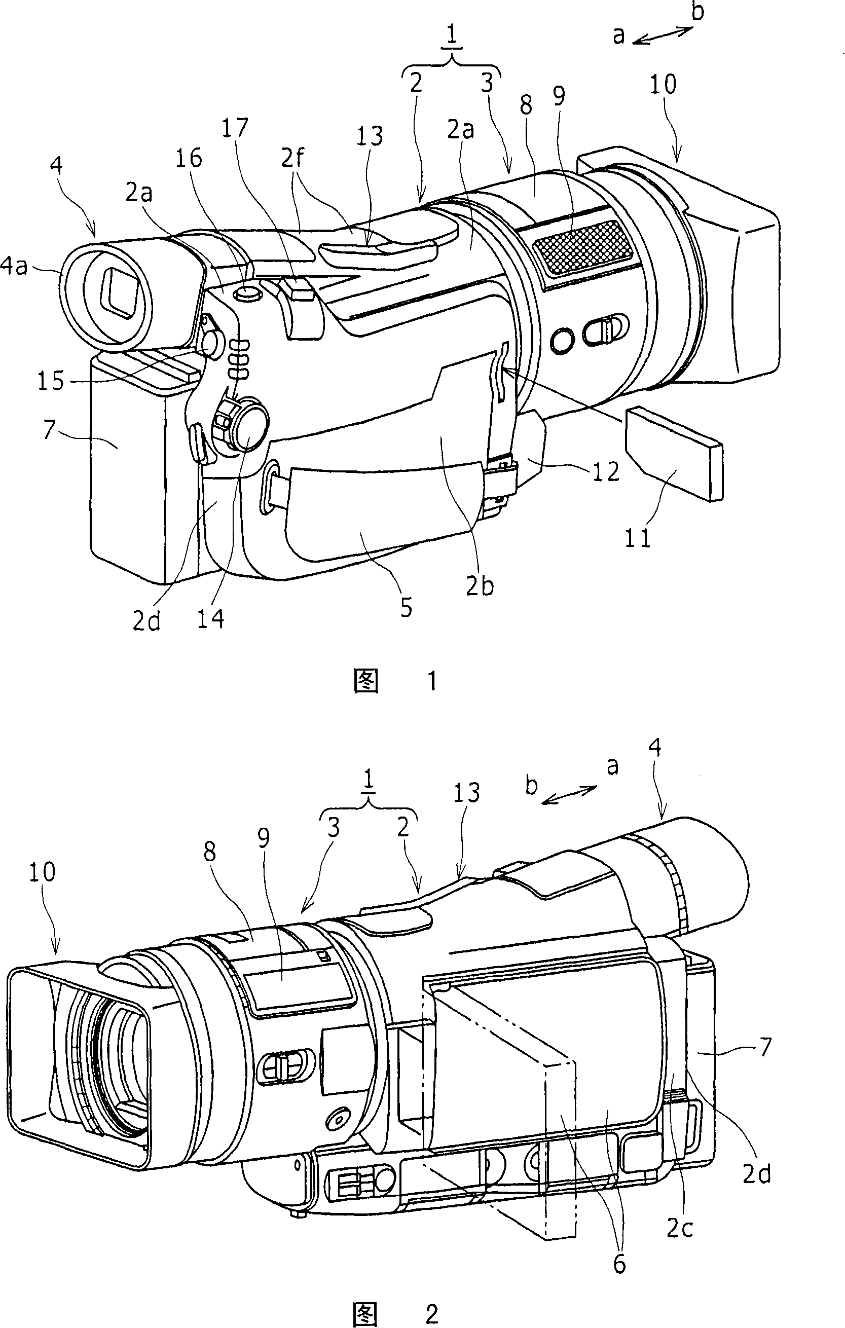
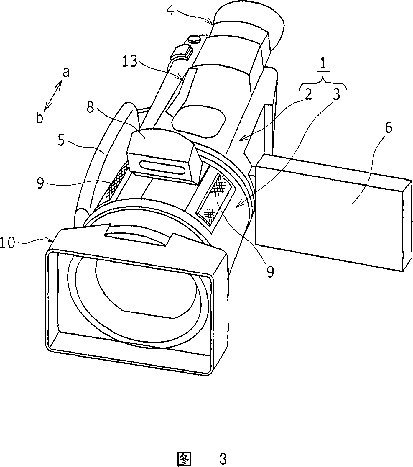
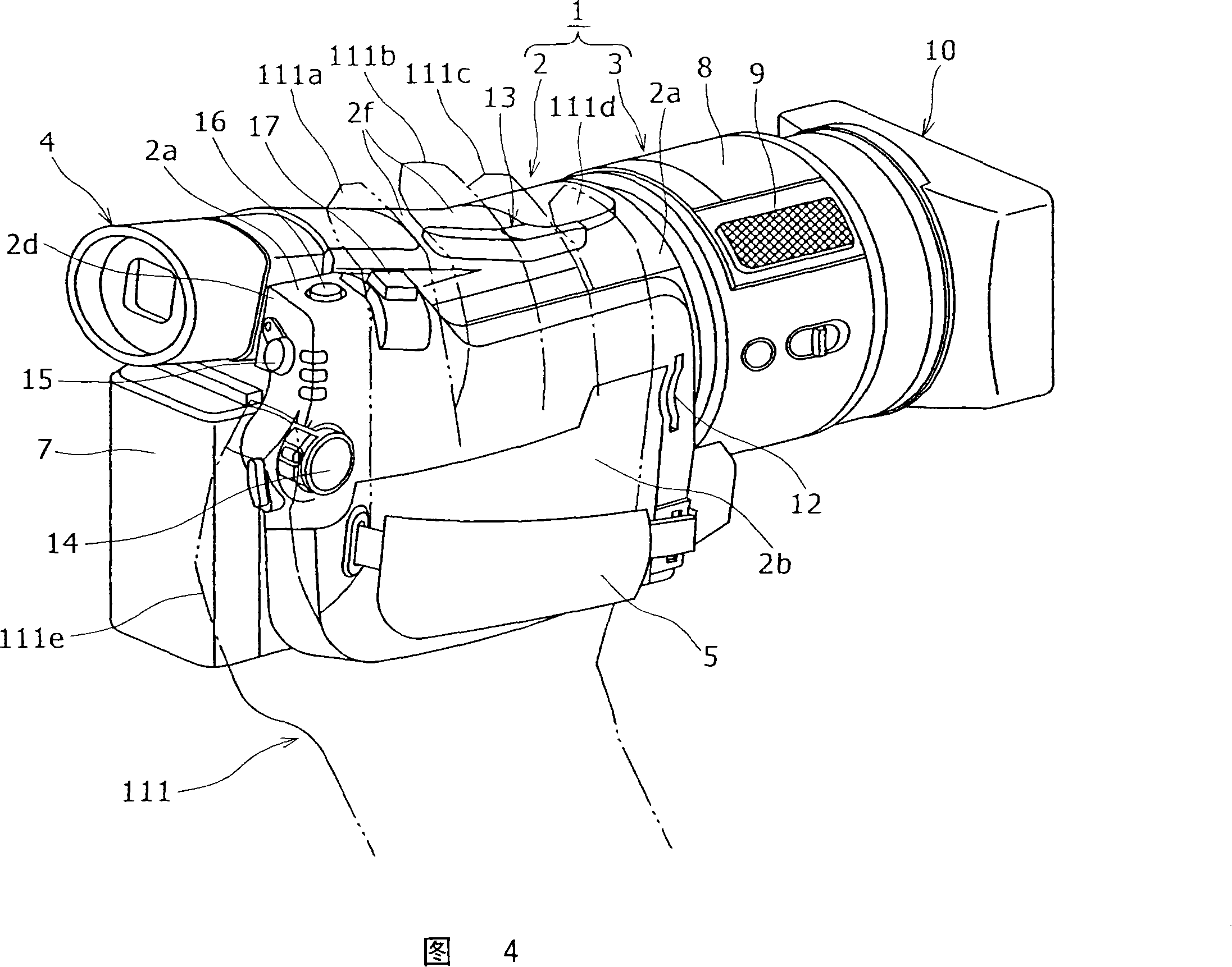
[0034] 1 to 3 show a video camera 1 as an example of an imaging device. FIG. 1 is a perspective view of the video camera 1 viewed from the side of the grip belt. FIG. 2 is a perspective view of the video camera 1 viewed from the monitor side. FIG. Stereo view of the state of use. The camera 1 includes a camera body 2, a front case 3 provided on the front side of the camera body 2, a viewfinder 4 provided on the upper surface 2a side of the camera body 2, and a camera body provided on the camera body 2. The grip belt 5 on the first side 2b, the monitor 6 provided on the second side 2c of the camera main body 2 opposite to the first si...


PUM


Abstract

Microphone mechanisms are arranged on both side sections of a flash mechanism arranged on a front cabinet of a video camera, and the microphone mechanisms are housed in the front cabinet. The video camera (1) is provided with a camera main body section (2); the front cabinet (3) arranged on a front side of the camera main body section (2); a view finder (4) arranged on the side of an upper plane (2a) of the camera main body section (2); a grip belt (5) arranged on a first side plane (2b) of the camera main body section (2); and the flash mechanism (8) arranged on the camera main body section (2). In the front cabinet (3), the microphone mechanisms (9) are housed on the both right and left side sections by sandwiching the flash mechanism (8).

Description

technical field [0001] The present invention relates to an imaging device such as a video camera, and particularly relates to an imaging device capable of recording sound more stereoscopically by arranging microphone mechanisms on both sides of the imaging device via a strobe mechanism provided in a front case of the imaging device. Background technique [0002] As a video camera, as shown in FIG. 17 , it is known to provide a recess 103 for mounting the microphone main body 102 on the front surface side of the front case 101 of the video camera, and to assemble a pair of microphone main bodies 102 in the recess by aligning them laterally. 103 within the device. In addition, a weight ring 104 is attached to the outer peripheral portion of the microphone main body portion 102 . The microphone main body 102 having the weight ring 104 attached to its outer periphery is attached to a shock absorber 105 made of a rubber material such as an elastic body. [0003] The shock absor...

Claims


Application Information

Patent Timeline
Patent Type & Authority Applications(China)
IPC IPC(8): H04N5/225H04R1/02
CPCH04N5/2251H04N23/50H04R1/02G03B17/56
Inventor 堤裕加
Owner SONY GRP CORP
Features
  • Generate Ideas
  • Intellectual Property
  • Life Sciences
  • Materials
  • Tech Scout
  • Unparalleled Data Quality
  • Higher Quality Content
  • 60% Fewer Hallucinations
Learn More