Product transport apparatus

A technology for conveying equipment and products, applied in conveyors, vibrating conveyors, transportation and packaging, etc., can solve the problems of high manufacturing cost of product conveying equipment, increase the number of vibration applying mechanisms, etc., and achieve low product conveying equipment and realization cost. Effect

Inactive Publication Date: 2008-04-09
SANKYO SEISAKUSHO
View PDF5 Cites 3 Cited by
  • Summary
  • Abstract
  • Description
  • Claims
  • Application Information

AI Technical Summary

Problems solved by technology

However, if a vibration applying mechanism for applying vibration is respectively arranged for each conveying platform to vibrate each conveying plat

Method used


Image

  • Product transport apparatus
  • Product transport apparatus
  • Product transport apparatus

Examples


no. 1 example

[0135] (1) Construction example of product conveying equipment

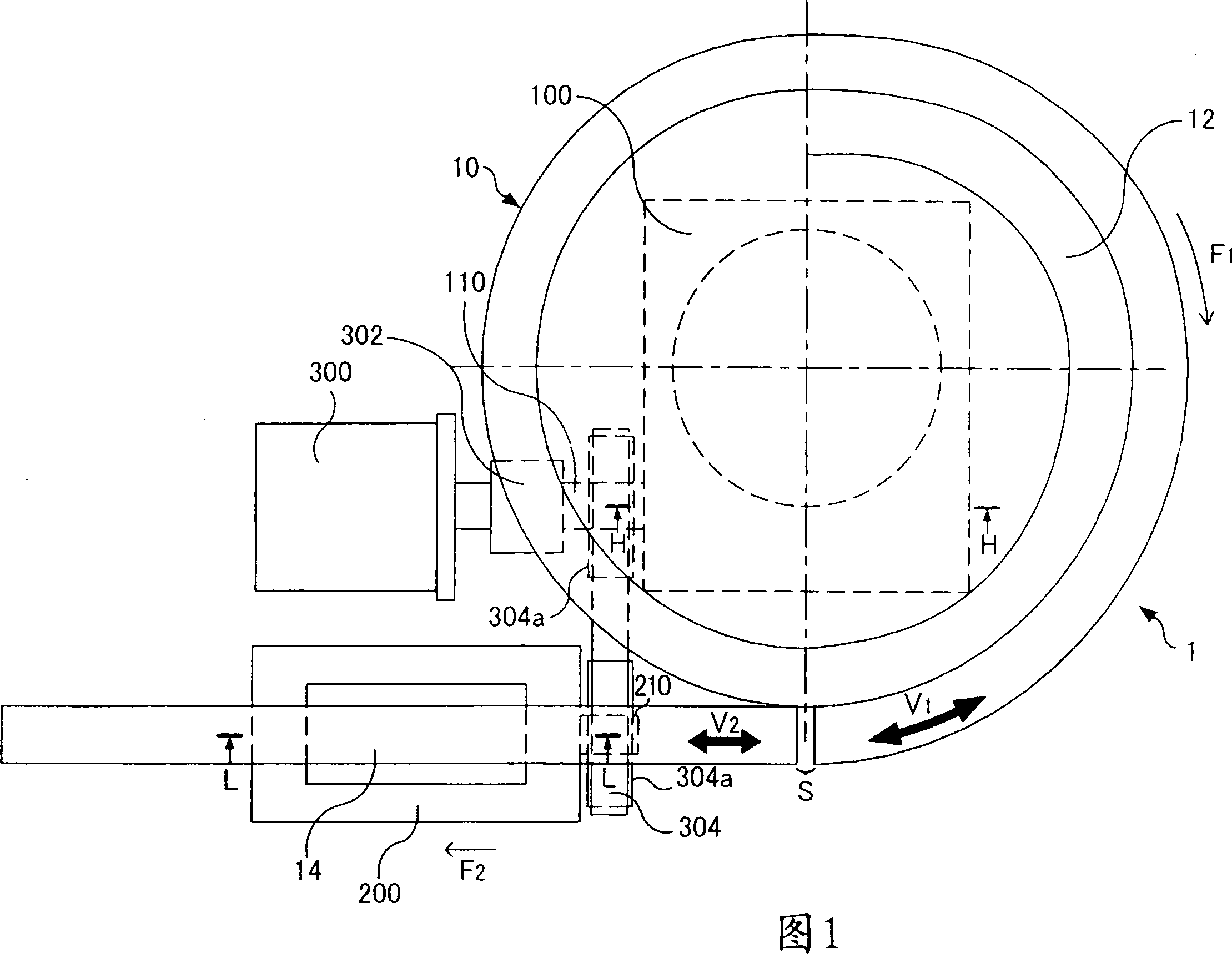
[0136] First, an example of the configuration of the product delivery device 1 according to the present embodiment is explained with reference to FIG. 1 . FIG. 1 is a schematic top view of the product conveying device 1 .

[0137] As shown in FIG. 1 , the product conveyance apparatus 1 includes: a conveyance part 10 ; a rotary feeder 100 ; a linear feeder 200 ; and a drive motor 300 serving as a single drive source. The rotary feeder 100 and the linear feeder 200 are examples of a vibration applying unit. That is, the product conveyance apparatus 1 is arranged with a plurality of (two in this embodiment) vibration applying sections. In this product conveying apparatus 1, the products W placed on the conveying portion 10 (more specifically, the conveying surface located at the upper end of the conveying portion 10) are conveyed in a state that they are in a predetermined conveying direction (arrow in FIG. 1 The...

no. 3 example

[0331] (3) Construction example of product conveying equipment

[0332] First, the product delivery device 2001 according to the present embodiment will be explained in general with reference to FIG. 29 . Accompanying drawing 29 is the schematic diagram of the product delivery device 2001 of this embodiment, schematically shows the top view (upper view) and the side view (lower view) of the product delivery device 2001 in the figure. In the lower view in Figure 29, the arrows indicate the vertical direction.

[0333] The product conveying device 2001 of this embodiment includes an elliptical conveying path (also referred to as an "elliptical track") as shown in FIG. 29 , which is a device for conveying products along the elliptical track. The elliptical circular path is formed by a plurality of delivery platforms (more specifically, a first delivery platform 2012 , a second delivery platform 2014 , a third delivery platform 2016 and a fourth delivery platform 2018 which will ...


PUM


Abstract

A product transport apparatus is provided that includes a transport section (10) that oscillates in a transport direction and in a vertical direction in order to transport a product; a plurality of oscillation imparting sections (100,200) including a first cam mechanism (140,240) for causing the transport section to oscillate in the transport direction and a second cam mechanism (150,250) for causing the transport section to oscillate in the vertical direction; and a single driving source (300) that drives the plurality of oscillation imparting sections.

Description

[0001] Cross References to Related Applications [0002] The present invention claims Japanese patent application No.2006-273011 submitted on October 4, 2006, Japanese patent application No.2007-49756 submitted on February 28, 2007, Japanese patent application No. 2007 submitted on February 28, 2007 .2007-49757, which patent applications are hereby incorporated by reference. technical field [0003] No invention relates to product delivery equipment. Background technique [0004] A known product conveying apparatus includes: a conveying portion that vibrates in the conveying direction and vertical direction; and a vibration applying portion. The vibration applying part includes a first cam mechanism for vibrating the conveying part in the conveying direction and a second cam mechanism for vibrating the conveying part in the vertical direction to convey the product (for example, refer to the publication No. 2006-124111 to be examination of Japanese patent applications). Th...

Claims


Application Information

Patent Timeline
IPC IPC(8): B65G27/04B65G27/18B65G27/34
Inventor 加藤平三郎加藤寿尚
Owner SANKYO SEISAKUSHO
Why Eureka
Try Eureka