Sectional type porous ceramic dielectric gas fuel combusting device

A gas burner, porous ceramic technology, applied in the direction of gas fuel burners, burners, combustion types, etc., can solve the problems of small pore size, tempering, and easy blocking of porous media, achieve effective anti-tempering or explosion, improve The effect of the safety factor

Inactive Publication Date: 2010-06-02
NORTHEASTERN UNIV LIAONING
View PDF6 Cites 6 Cited by
  • Summary
  • Abstract
  • Description
  • Claims
  • Application Information

AI Technical Summary

Problems solved by technology

Although the burner with this structure is better than the metal fiber surface burner, it solves the problem that the burner is prone to backfire during use, and the adjustment range of fuel and air is small, and the thermal efficiency is low.
However, the use of this porous media burner still has the following defects: the porous media has a small aperture and is very easy to block, so most of the current burners are only used for a single pure gas fuel, and most of the actual production needs to burn dust content High gas or mixed gas, which brings limitations to the practical application of porous media burners

Method used


Image

  • Sectional type porous ceramic dielectric gas fuel combusting device
  • Sectional type porous ceramic dielectric gas fuel combusting device
  • Sectional type porous ceramic dielectric gas fuel combusting device

Examples


example 1

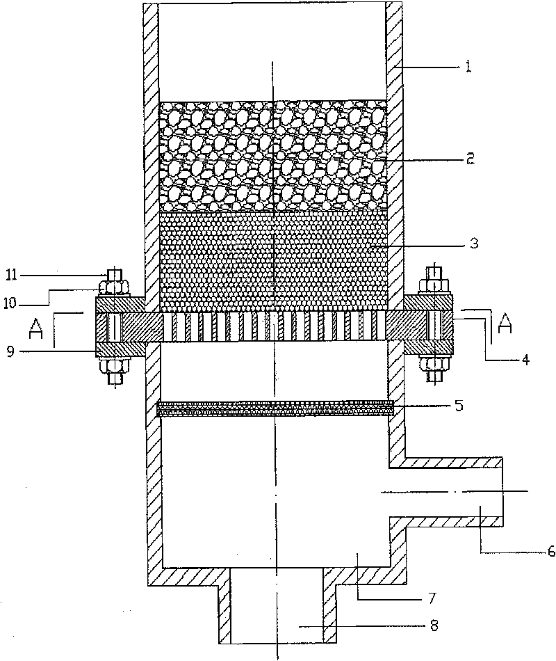
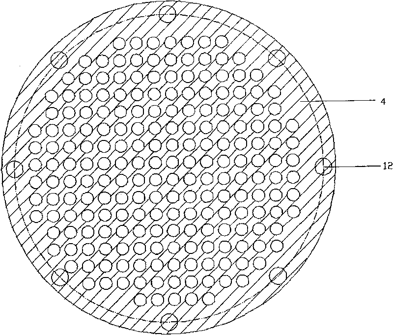
[0015] Example 1, such as figure 1 , figure 2 As shown, the burner is composed of a burner shell, a ceramic porous medium in the large hole area, a ceramic porous medium in the small hole area, a porous plate, a dust removal metal mesh, an air pipe, a premixing chamber, and a gas pipe. The burner shell is divided into upper and lower parts by a porous plate. Inside the cavity formed by the upper part of the burner shell, ceramic porous media in the large-pore area are arranged in sequence from top to bottom, and the ceramic porous media in the large-pore area are placed below On the ceramic porous medium in the small hole area, the two are in close contact. The ceramic porous medium in the small hole area is placed on the porous plate and is in close contact. There is a cavity between the upper surface of the ceramic porous medium in the large hole area and the top surface of the burner casing. The perforated plate is sandwiched between the upper and lower parts of the bur...

example 2

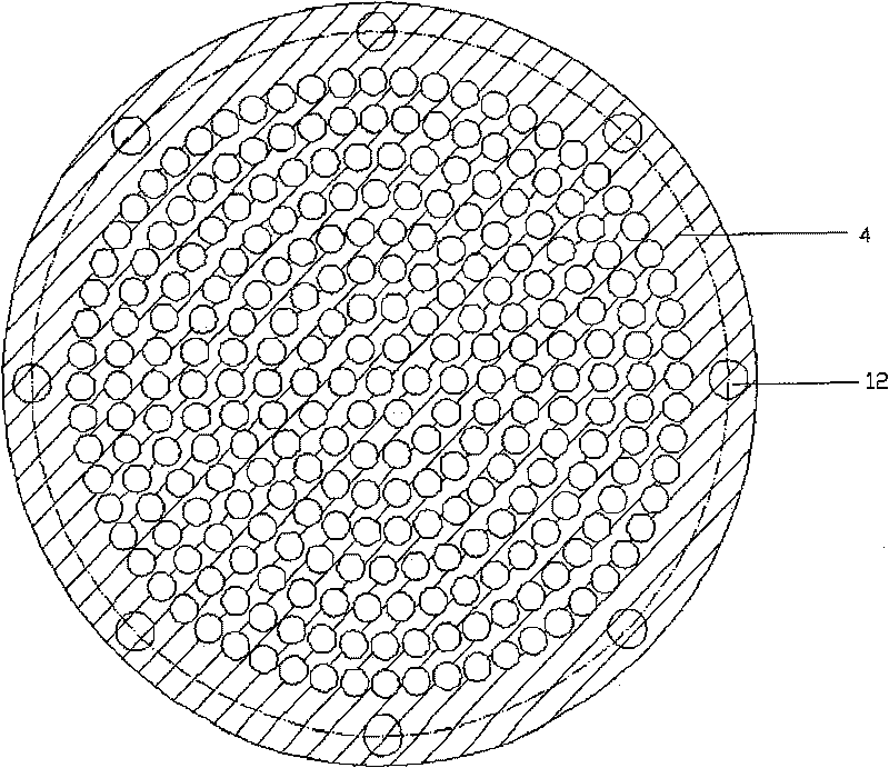
[0020] The structure of the burner is the same as Example 1. The difference is: the ceramic material in the large-pore area is calcium oxide-based zirconia, with an average pore diameter of 4 mm, a porosity of 85%, and the arrangement of the pores is disordered; the ceramic material in the small-pore area is calcium oxide-based zirconia, with an average pore diameter of 4 mm. The hole is 0.4mm, the porosity is 80%, and the arrangement of the holes is disordered; the material of the porous plate is low carbon steel alloy, the average pore size is 4mm, and the porosity is 83%. The arrangement of the holes is straight-through and arranged in a ring around the center. The axial section of the burner shell is square, and its material is cast iron. The premix chamber is fitted with stainless steel dust removal metal brushes.

[0021] Burner application: the combustion gas is coke oven gas, and the gas flow rate is 800m 3 / h, the air flow rate is 1500m 3 / h. The content of unbur...

example 3

[0022] Example 3: The burner structure is the same as Example 2. The difference is: silicon carbide is used as the ceramic material in the large-pore area, silicon carbide is used as the ceramic material in the small-pore area, and metal aluminum is selected as the porous plate material, with an average pore diameter of 3mm and a porosity of 84%. The axial section of the burner shell is hexagonal, and its material is high-temperature resistant stainless steel.

[0023] Burner application: the combustion gas is natural gas, and the gas flow rate is 2000m 3 / h, the air flow is 3000m 3 / h. Burning effect is the same as Example 2.


PUM

PropertyMeasurementUnit
pore sizeaaaaaaaaaa
pore sizeaaaaaaaaaa
pore sizeaaaaaaaaaa

Abstract

The invention relates to a multi-stage multi-aperture ceramic dielectric gas fuel inflamer which includes an inflamer shell, a dust-removing wire netting or a metal brush, an air pipeline, a premixingchamber and a fuel gas pipeline. The invention is mainly characterized in that the inflamer shell is divided into an upper part and a lower part with a multi-aperture plate as a boundary. The inner part of the empty cavity at the upper part of the inflamer shell is sequentially provided with a ceramic multi-aperture dielectric of the large-aperture area which is arranged above a ceramic multi-aperture dielectric of the small-aperture area and the ceramic multi-aperture dielectric of the small-aperture area is arranged on the multi-aperture plate. The dust-removing wire netting or the metal brush is arranged under the multi-aperture plate and in the inflamer shell. The multi-aperture plate is imbedded into the middle of the upper and lower parts of the inflamer shell. The surrounding of the multi-aperture plate extends to the outside of the inflamer shell. The invention has the advantage that the multi-stage multi-aperture ceramic dielectric gas fuel inflamer has a higher thermal valuerange, thereby both the gas of a low thermal value or bum gas fuel and the gas of a higher thermal value can be burnt. The multi-aperture plate added in the inflamer has played a good role of radiating and can effectively prevent backfire or explosion.

Description

technical field [0001] The invention relates to a burner, in particular to a segmented porous ceramic medium gas fuel burner. Background technique [0002] At present, the combustion of gaseous fuels in my country's industrial production is mainly space combustion characterized by free flames. In this combustion mode, the temperature gradient near the flame surface is steep and unevenly distributed, and the existence of local high-temperature areas causes a large amount of NO X Formation, incomplete combustion and low thermal efficiency, poor combustion stability. Now, the technology of adding porous media in the burner has gradually been paid attention to. Premixed combustion in porous media has many advantages: smaller lean burn limit, higher combustion rate and stability, wide load adjustment range, high combustion intensity, small burner volume, etc., and the nitrogen and sulfur in the combustion products Therefore, premixed combustion in porous media has great potenti...

Claims


Application Information

Patent Timeline
Patent Type & Authority Patents(China)
IPC IPC(8): F23D14/02F23D14/46
Inventor 李本文刘慧董帅饶文涛
Owner NORTHEASTERN UNIV LIAONING
Why Eureka
Try Eureka