

Ultrasonic actuator
An actuator, ultrasonic technology, applied in piezoelectric/electrostrictive/magnetostrictive devices, piezoelectric effect/electrostrictive or magnetostrictive motors, generators/motors, etc., can solve the problem of hindering piezoelectric Eliminate problems such as component bending vibration and efficiency reduction, and achieve the effect of suppressing obstacles and improving efficiency
- Summary
- Abstract
- Description
- Claims
- Application Information
AI Technical Summary
Benefits of technology
Problems solved by technology
Method used
Image

Examples
Embodiment 1
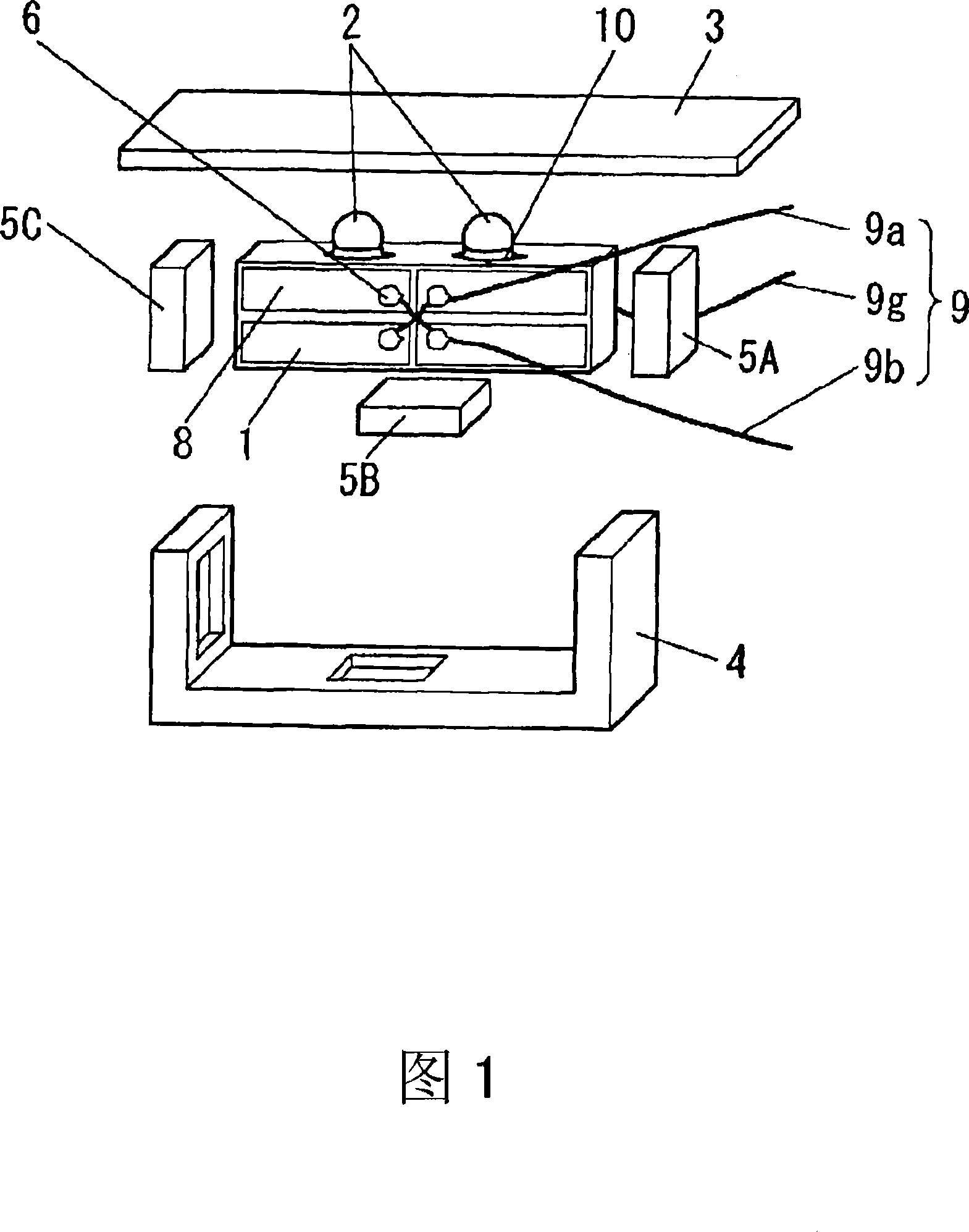
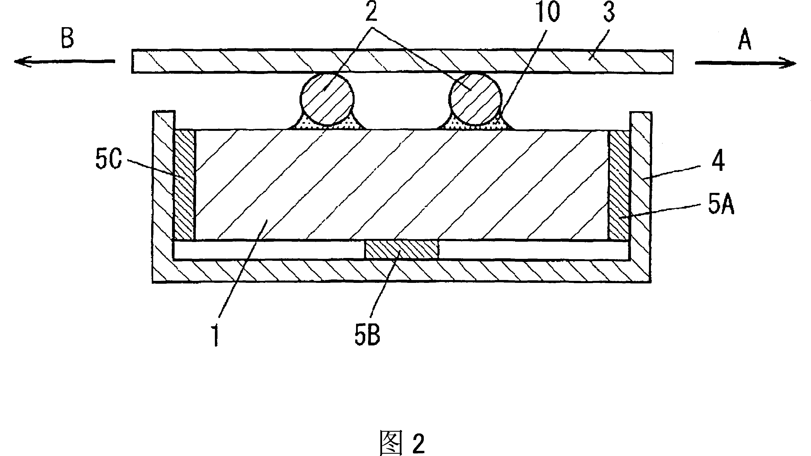
FIG. 1 is an exploded perspective view of an ultrasonic actuator in Embodiment 1 of the present invention, and FIG. 2 is a cross-sectional view of FIG. 1 .
[0022] In FIGS. 1 and 2 , spherical driving parts 2 and 2 are provided at two places on the surface of a piezoelectric element 1 made of a piezoelectric material such as PZT (lead zirconate titanate) or crystal.
[0023] A power supply electrode 8 divided into four is provided on the front surface of the piezoelectric element 1 , and an integral electrode (not shown) is provided on the rear surface of the piezoelectric element 1 . Lead wires 9 are connected to the power supply electrodes 8 and the bulk electrodes with solder 6 , and the lead wires 9 are led to the outside through through holes (not shown) provided in the case 4 . When an AC voltage of a specific frequency is applied to the power supply electrode 8 and the entire electrode of the piezoelectric element 1 through the lead wire 9 , the piezoelectric element 1 ...
Embodiment 2
Next, the ultrasonic actuator according to the second embodiment of the present invention will be described.
[0039] Although in the above-mentioned first embodiment, each drive unit 2 is attached to the piezoelectric element 1 in point contact with the adhesive 10, in the ultrasonic actuator according to the second embodiment, as shown in FIG. 7, The annular body 71 is arranged around each drive unit 2 . In short, the annular body 71 is arranged around the contact point between each drive unit 2 and the piezoelectric element 1 . That is, each driving unit 2 is not only attached to the piezoelectric element 1 in a point contact state, but also attached to the piezoelectric element 1 through the annular body 71 . The annular body 71 is attached to each of the drive units 2 and the piezoelectric element 1 in line contact. Furthermore, each drive unit 2 and the annular body 71 , and the annular body 71 and the piezoelectric element 1 are attached together with the adhesive 10 ....
Embodiment 3
Next, the ultrasonic actuator according to the third embodiment of the present invention will be described.
[0043] In the above first and second embodiments, the case where a spherical shape is used as the shape of the driving portion 2 has been described, but a cylindrical driving portion can also be used. At this time, each drive unit 2 is arranged so that the axis of the cylinder substantially perpendicularly intersects the plane on which each drive unit 2 performs approximately elliptical motion (that is, the plane on which the piezoelectric element 1 performs bending vibration), and each drive unit 2 It is mounted on the surface of the piezoelectric element 1 (see FIG. 10 ). The cross-sectional view at this time is the same as that in FIG. 2 . In addition, it is preferable to fix each of the columnar driving parts 2 to the piezoelectric element 1 with the same adhesive 10 as that used for the spherical shape. In this way, each drive unit 2 is mounted on the upper surfa...
PUM
 Abstract
Description
Claims
Application Information