Optical element

A technology of optical components and switching components, applied in the field of optical components

Active Publication Date: 2008-04-30
NEC LCD TECH CORP
View PDF3 Cites 25 Cited by
  • Summary
  • Abstract
  • Description
  • Claims
  • Application Information

AI Technical Summary

Problems solved by technology

Therefore, even when the micro window is attached to the display screen, when viewed obliquely from a position in front of the display screen, the right end of the display screen is disadvantageously visible

Method used


Image

  • Optical element
  • Optical element
  • Optical element

Examples


Embodiment Construction

[0038] (first exemplary embodiment)

[0039] Fig. 4 is a cross-sectional view showing an optical element according to a first exemplary embodiment of the present invention. FIG. 5 is a plan view of the microwindow shown in FIG. 4 .

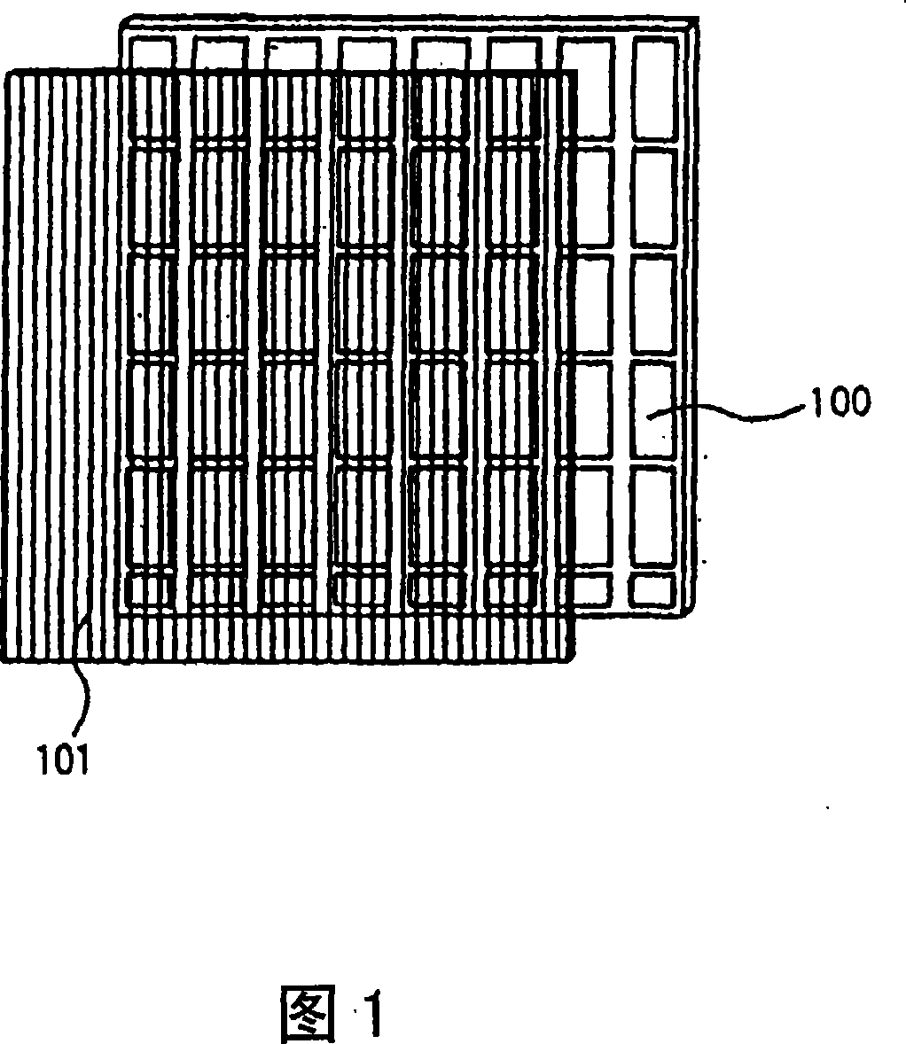
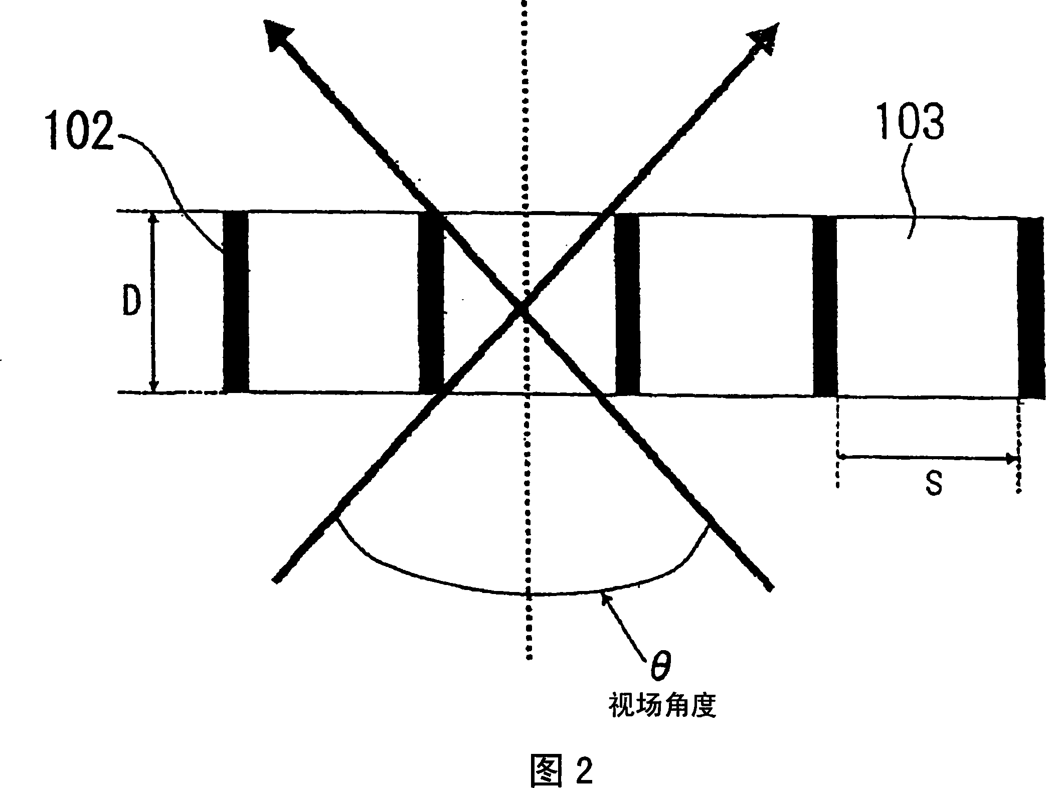
[0040] The optical element of this exemplary embodiment comprises a microwindow 1 and a diffuser layer 4 attached to the microwindow 1, and the microwindow 1 has a linear light-absorbing material layer 2 and a linear transparent layer 3 arranged alternately along one reverse direction. periodic structure. In the microwindow 1 of this exemplary embodiment, the light absorbing layer 2 and the transparent layer 3 are periodically arranged at a fixed interval. Furthermore, in the microwindow 1 of this exemplary embodiment, the ratio of the width S of the transparent layer 3 to the thickness D of the microwindow 1 is smaller than that of typical microwindows. Therefore, at both ends of the microwindow 1 in this exemplary embodiment, the viewing angl...


PUM

PropertyMeasurementUnit
thicknessaaaaaaaaaa
widthaaaaaaaaaa

Abstract

An optical element comprises: a micro window comprising a transparent layer and a photoabsorption layer arranged alternately, wherein the photoabsorption layer limits directive spectrum of light shooting through the transparent layer; a diffuseness layer disposed on the micro window. Visual field angle varies according to such manner: visual field angle of light passing external zone of optical element is smaller than visual field angle of light passing center zone of optical element.

Description

technical field [0001] The invention relates to an optical element comprising a microlouver which limits the range of directions of outgoing transmitted light. The present invention also relates to an illumination optical device using such an optical element, and a display device typified by a liquid crystal display (LCD) and a plasma display using such an optical element. Background technique [0002] Liquid crystal displays are used as display devices of various information processing devices such as mobile phones, personal digital assistants (PDAs), automated teller machines (ATMs), and personal computers. In recent years, liquid crystal displays in which the angle of field of view is large have been commercially available. [0003] When a single display screen is viewed by a plurality of viewers, it is effective to use a liquid crystal display in which the viewing angle is large. However, in devices designed for personal use, such as mobile phones, a larger field of vi...

Claims


Application Information

Patent Timeline
Patent Type & Authority Applications(China)
IPC IPC(8): G02B5/00G02F1/1333
CPCG02F1/133504G02B5/005G02B5/0252G02F1/133524G02B5/0231G02B5/0278
Inventor 三村广二住吉研
Owner NEC LCD TECH CORP
Why Eureka
Try Eureka