Reflection type liquid-crystal display device

a display device and liquid crystal display technology, applied in the direction of identification means, instruments, optics, etc., can solve the problems of difficult viewing of display, short backward transmission efficiency, display screen darkening, etc., and achieve the effect of easy balanced

Inactive Publication Date: 2009-03-10
NITTO DENKO CORP
View PDF21 Cites 16 Cited by
  • Summary
  • Abstract
  • Description
  • Claims
  • Application Information

AI Technical Summary

Benefits of technology

[0011]On the other hand, the slope reflection type optical path control layer according to the present invention mainly uses light exhibiting a peak in the regular reflection direction, and controls the optical path of the reflected light. Accordingly, the optical path control layer easily changes the optical path of the light with direc

Problems solved by technology

If no low-refractive-index transparent layer is provided in the display device, backward transmission efficiency runs short so that the display screen becomes darker and viewing of the display becomes difficult as the viewing point

Method used


Image

  • Reflection type liquid-crystal display device
  • Reflection type liquid-crystal display device
  • Reflection type liquid-crystal display device

Examples


reference example 1

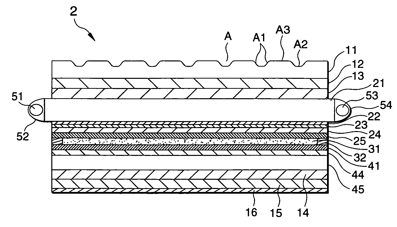
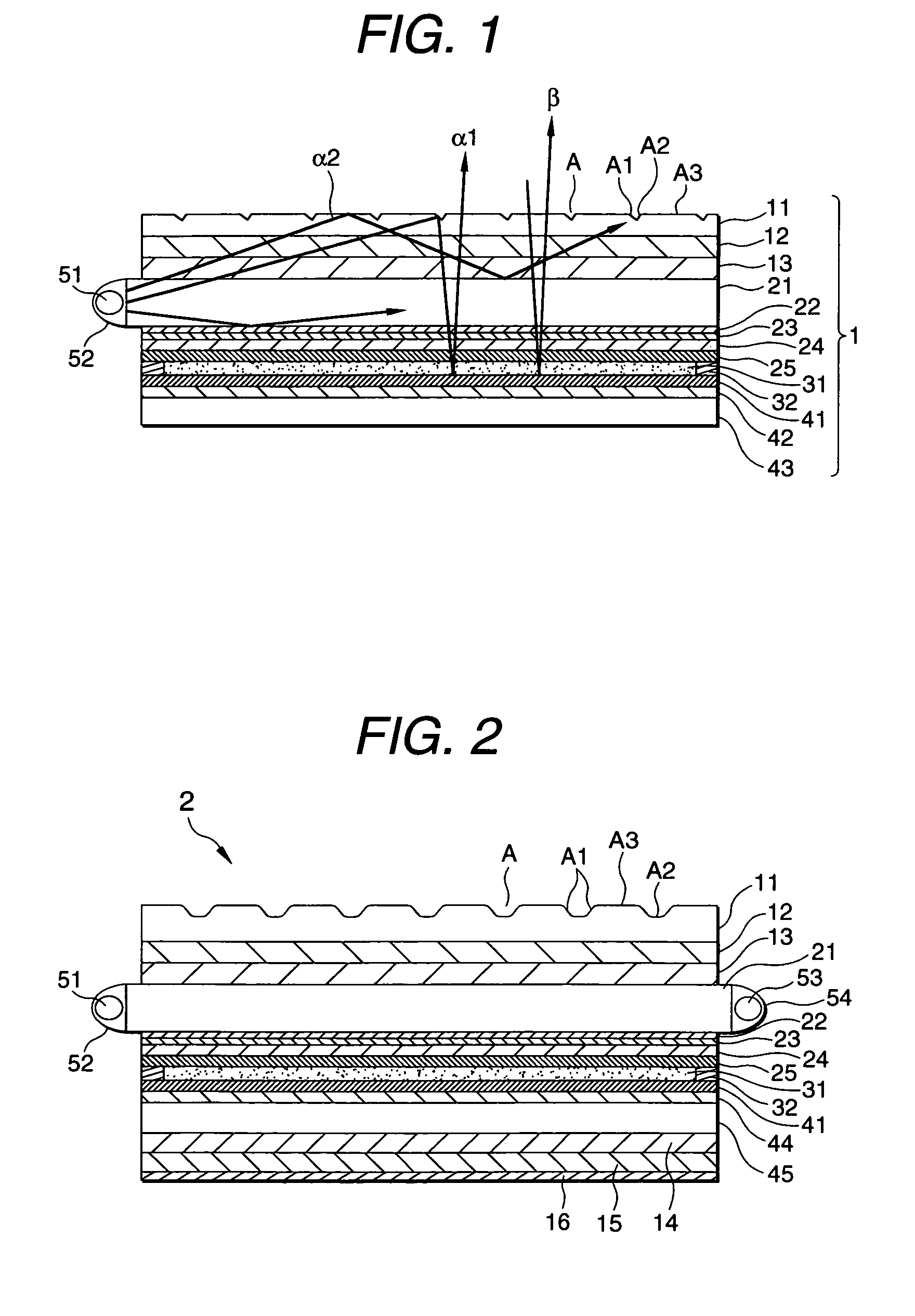
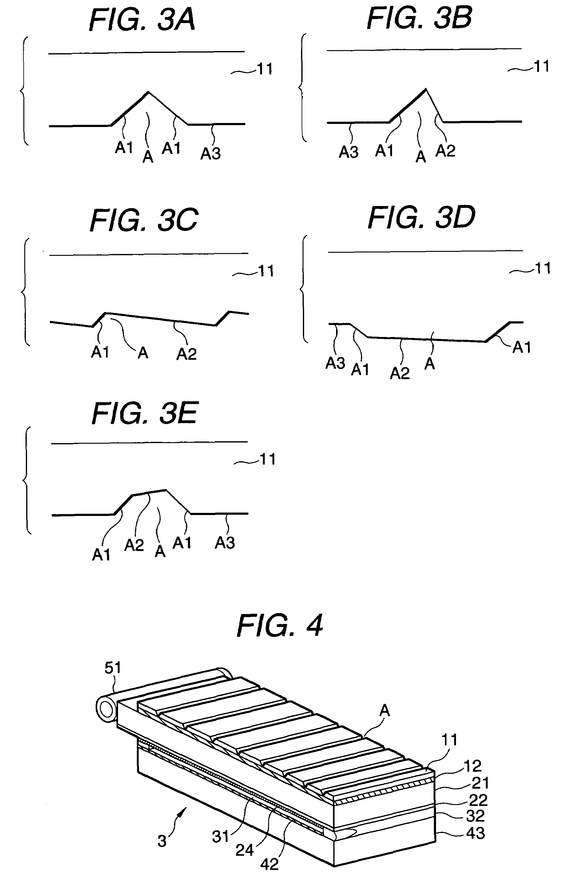
[0075]Magnesium fluoride was applied onto a non-alkali glass plate having a thickness of 0.7 mm and a refractive index of 1.52 by vacuum evaporation to thereby form a low-refractive-index transparent layer having a thickness of 600 nm and a refractive index of 1.38 on the non-alkali glass plate. Red, blue and green stripe-like color filter layers and an ITO transparent electrically conductive layer were successively formed on the low-refractive-index transparent layer. Then, the transparent electrode thereof was divided by etching and a polyvinyl alcohol solution was applied thereon by spin coating. The dried film obtained thus was subjected to a rubbing treatment. Thus, a visual-side substrate was obtained. On the other hand, an ultraviolet-curable resin layer was formed on a non-alkali glass plate in the same manner as described above. After the ultraviolet-curable resin layer was subjected to a surface-roughening treatment, aluminum vapor was deposited on the ultraviolet-curable ...

reference example 2

[0077]A normally white reflection type liquid-crystal display panel provided with a cold-cathode tube held on one of side surfaces of the panel was obtained in the same manner as in Reference Example 1 except that the thickness of the low-refractive-index transparent layer made of magnesium fluoride was changed to 300 nm.

reference example 3

[0078]A normally white reflection type liquid-crystal display panel provided with a cold-cathode tube held on one of side surfaces of the panel was obtained in the same manner as in Reference Example 1 except that the thickness of the low-refractive-index transparent layer made of magnesium fluoride was changed to 100 nm.


PUM


Abstract

A reflection type liquid-crystal display device has a reflection type liquid-crystal display panel, at least one illuminator, and an optical path control layer. The reflection type liquid-crystal display panel includes a liquid-crystal cell and a reflector, the liquid-crystal cell having a visual-side substrate, a back-side substrate and a liquid crystal. The visual-side substrate includes a transparent substrate, a transparent layer lower in reflective index than the transparent substrate, and a transparent electrode. The back-side substrate has an electrode, and the liquid crystal is held between the visual-side and back-side substrates so that respective electrode sides of the visual-side and back-side substrates are disposed opposite to each other. The reflector is disposed on the back-side substrate side. The illuminator is disposed on one of side surfaces of the reflection type liquid-crystal display panel. The optical path control layer has a repetitive structure of optical path changing slopes on an outer side of the visual-side substrate and being higher in refractive index than the low-refractive-index transparent layer. Each of the optical path changing slopes is inclined at an inclination angle in a range of from 35 to 48 degrees with respect to a reference plane of the visual-side substrate.

Description

BACKGROUND OF THE INVENTION[0001]1. Field of the Invention[0002]The present invention relates to a reflection type liquid-crystal display device which can be easily reduced both in thickness and in weight, which is excellent in display quality and which can be used both in an external light mode and in an illumination mode.[0003]The present application is based on Japanese Patent Application No. 2000-140320, which is incorporated herein by reference.[0004]2. Description of the Related Art[0005]Further reduction in thickness and weight of reflection type liquid-crystal display devices has been demanded for the purpose of reduction in size and weight of portable personal computers, portable telephone sets, etc. In the meanwhile, it was difficult to reduce the thickness and weight of a background-art reflection type liquid-crystal device provided with a front-lighting system using a side-light type light pipe (see Unexamined Japanese Patent Publication No. Hei. 11-250715) Incidentally,...

Claims


Application Information

Patent Timeline
IPC IPC(8): G02F1/1335F21V8/00G02B6/00G02F1/13357G09F9/00
CPCG02B6/0038G02F1/133615G02B6/0056G02F1/133528G02F2001/133616G02F1/133616G02F1/133553
Inventor UMEMOTO, SEIJIARIYOSHI, TOSHIHIKOSUZUKI, TAKAO
Owner NITTO DENKO CORP
Why Eureka
Try Eureka