Display device

A technology of a display device and a microlens array, which is used in static indicators, optics, instruments, etc., can solve the problems of unsatisfactory visual effects, poor confidentiality, and inability to provide different images.

Inactive Publication Date: 2008-04-30
北京超多维科技有限公司
View PDF1 Cites 23 Cited by
  • Summary
  • Abstract
  • Description
  • Claims
  • Application Information

AI Technical Summary

Problems solved by technology

Although the above-mentioned device can watch different images in different directions, the images seen in the visible range are alternate, and different images will appear at a slight deviation from a certain angle. The visual range of the same image is very narrow. The visual effect is obviously unsatisfactory, and it cannot stably provide different images for two people in different directions in practical applications
Due to a slight deviation of an angle, another image can be seen, and it is obviously not good for security when applied to a security display.

Method used


Image

  • Display device
  • Display device
  • Display device

Examples


Embodiment 1

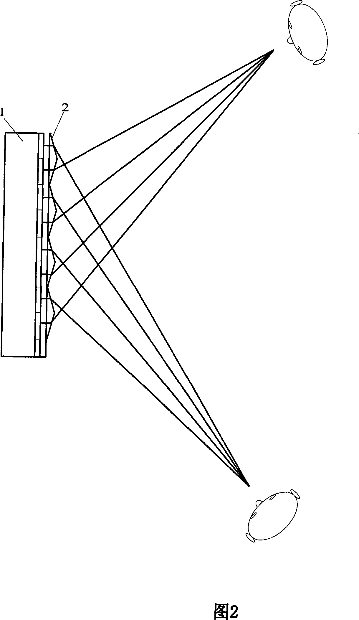
[0014] Embodiment 1: Referring to FIG. 2 , the display device in this embodiment includes a display panel 1 for providing images and a microlens array 2 , wherein each column of the microlens array is a triangular prism mirror. It can be seen from the light path diagram in the figure that the light rays emitted by two immediately adjacent columns of pixels are refracted by the prism mirror, and then emitted from two directions respectively, and the two adjacent columns of pixels belong to different images.

Embodiment 2

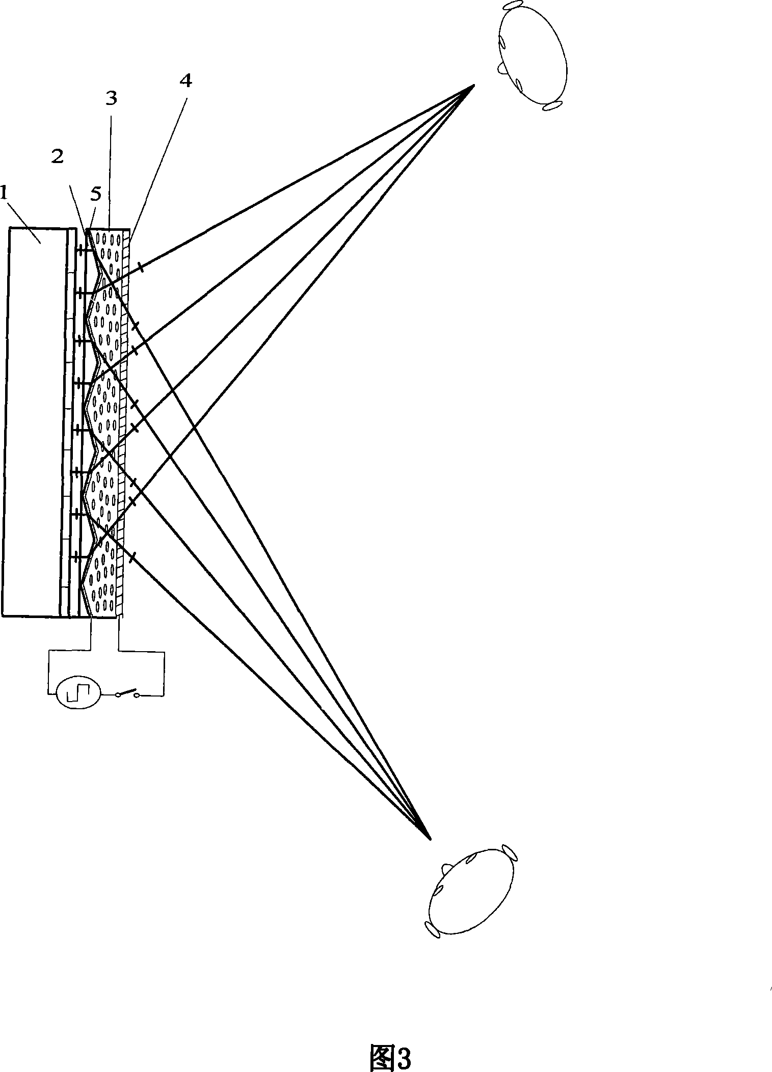
[0015] Embodiment 2: As a further improvement to the above-mentioned Embodiment 1, referring to FIG. 3 , the display device in this embodiment includes a display panel 1 for providing images, a microlens array (prismatic mirror array) 2, a birefringent material 3 and a transparent electrode 4 and 5, wherein the light emitted by the display panel is linearly polarized light, if the light emitted by the display panel is natural light, a polarizer needs to be placed between the display panel and the microlens array, and the natural light emitted by the display panel In this embodiment, the birefringence material is nematic liquid crystal, and the nematic liquid crystal is oriented so that the polarization direction of the linearly polarized light is the same as that of the nematic phase in the absence of an electric field. The alignment direction of the liquid crystal of the liquid crystal (direction loss or optical axis direction) is the same, the alignment layer is not shown sep...


PUM


Abstract

The invention relates to a displaying device which comprises a device which provides image light source and a microlens array which is arranged at the front part of the device which provides image light source. The microlens array is composed of triangle-shaped prism lenses. Two adjacent lines of pixels are refracted to different directions by the microlens array. The invention also can further comprise a first transparent electrode and a second transparent electrode which are used for controlling an electric field and double-refractive material which is arranged between the first transparent electrode and the second transparent electrode. The light beam which is sent out by the device which provides image light source directly transmittedly or refractively passes through the microlens array and the double-refractive material in the area in which the double-refractive material is arranged under the condition that an electric field exists or no electric field exists. The conditions that two images can be displayed in different directions, and the same image can be displayed in the same direction can be controlled. The invention has the advantages of simple structure and wide application.

Description

technical field [0001] The invention relates to the display field, in particular to a display device capable of displaying different images in different directions of a screen. Background technique [0002] With the continuous development of display technology, the display of images is becoming more and more diversified, from the display of flat images to the display of stereoscopic images, as well as dual-view or multi-view display, and the application of dual-view and multi-view display is usually kept secret. For display applications, the main viewing angle is the front, and the side is used to interfere with other people’s peeping. As shown in FIG. Each opening 22a of the shielding part 22 is designed to guide the image for the center to the center position (along the front direction) and the image for the side to the side position, wherein the liquid crystal shielding part can be a grating or other similar devices. Although the above-mentioned device can watch differen...

Claims


Application Information

Patent Timeline
Patent Type & Authority Applications(China)
IPC IPC(8): G02B27/22G02F1/13G02F1/133H04N13/00
Inventor 杨扬
Owner 北京超多维科技有限公司
Why Eureka
Try Eureka