Transformer

A technology of transformers and iron cores, applied in the field of transformers, can solve problems such as increasing the cost of transformer components

Inactive Publication Date: 2008-04-30
DELTA ELECTRONICS INC
View PDF0 Cites 12 Cited by
  • Summary
  • Abstract
  • Description
  • Claims
  • Application Information

AI Technical Summary

Problems solved by technology

Therefore, a transformer 2 is additionally developed, such as figure 2 As shown, it uses a flat circuit board 22 with a spiral circuit to generate electromagnetic induction through an electr...

Method used


Image

  • Transformer
  • Transformer
  • Transformer

Examples


Embodiment Construction

[0038] The following implementation manners will be described according to the related drawings of a transformer 3 in a preferred embodiment of the present invention, wherein the same components will be denoted by the same reference symbols.

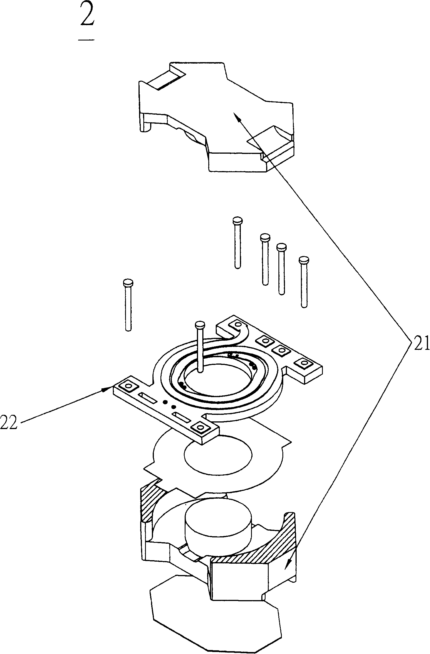
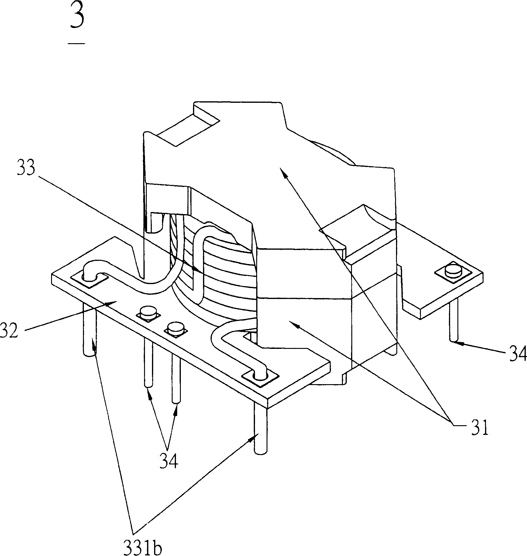
[0039] Please refer to Figure 3A and Figure 3B As shown, a transformer 3 according to a preferred embodiment of the present invention includes a core set 31 , a circuit board 32 and a winding set 33 , and the transformer 3 is used in an electronic device.

[0040] The iron core set has a first iron core 311 and a second iron core 312. After the two are clamped, a circuit board 32 and a winding group 33 are provided in the middle, wherein the winding group 33 further includes an insulating coil. 331 and a conductive sheet 332, and the conductive sheet 332 is placed between the double-layer structure formed after the insulating coil 331 is wound. The first iron core 311 and the second iron core 312 of the iron core group 31 have a rais...


PUM


Abstract

The invention provides a transformer, including an iron core group consisting of a first iron core and a second iron core, which are configured oppositely to form an containing space; a circuit board with a plurality of through-holes and located in the containing space; and a winding group located in the containing space, including an insulation coil with extension portions, each passes corresponding through the trough-holes; and a plurality of conductive sheets arranged in the insulation coil.

Description

technical field [0001] The invention relates to a transformer capable of miniaturization and cost reduction, in particular to a transformer conforming to safety regulations. Background technique [0002] Transformers are electronic components often used in various electrical equipment, such as figure 1 As shown, the existing transformer 1 includes a winding base 11 (bobbin), a coil assembly 12 , a pin base 14 and an iron core 13 . The coil set 12 includes a primary coil and a secondary coil, both of which are respectively wound on the winding base 11 by a conductive wire, and the primary coil and the secondary coil are electromagnetically coupled to each other. The iron core group is composed of a first iron core 131 and a second iron core 132. The first iron core 131 and the second iron core 132 are respectively sleeved on the two ends of the winding base 11 and joined with each other to form an electromagnetic circuit. [0003] Generally speaking, the coil group is made...

Claims


Application Information

Patent Timeline
IPC IPC(8): H01F27/24H01F27/40
Inventor 魏伯佑
Owner DELTA ELECTRONICS INC
Why Eureka
Try Eureka