Supercharge Your Innovation With Domain-Expert AI Agents!

Reticle alignment and overlay for multiple reticle process

A mask and alignment mark technology, which is applied to the photolithographic process, instruments, and optomechanical equipment of the patterned surface, and can solve the problems of limiting wire density and difficulty in removal

Inactive Publication Date: 2008-04-30
LAM RES CORP
View PDF1 Cites 3 Cited by
  • Summary
  • Abstract
  • Description
  • Claims
  • Application Information

AI Technical Summary

Problems solved by technology

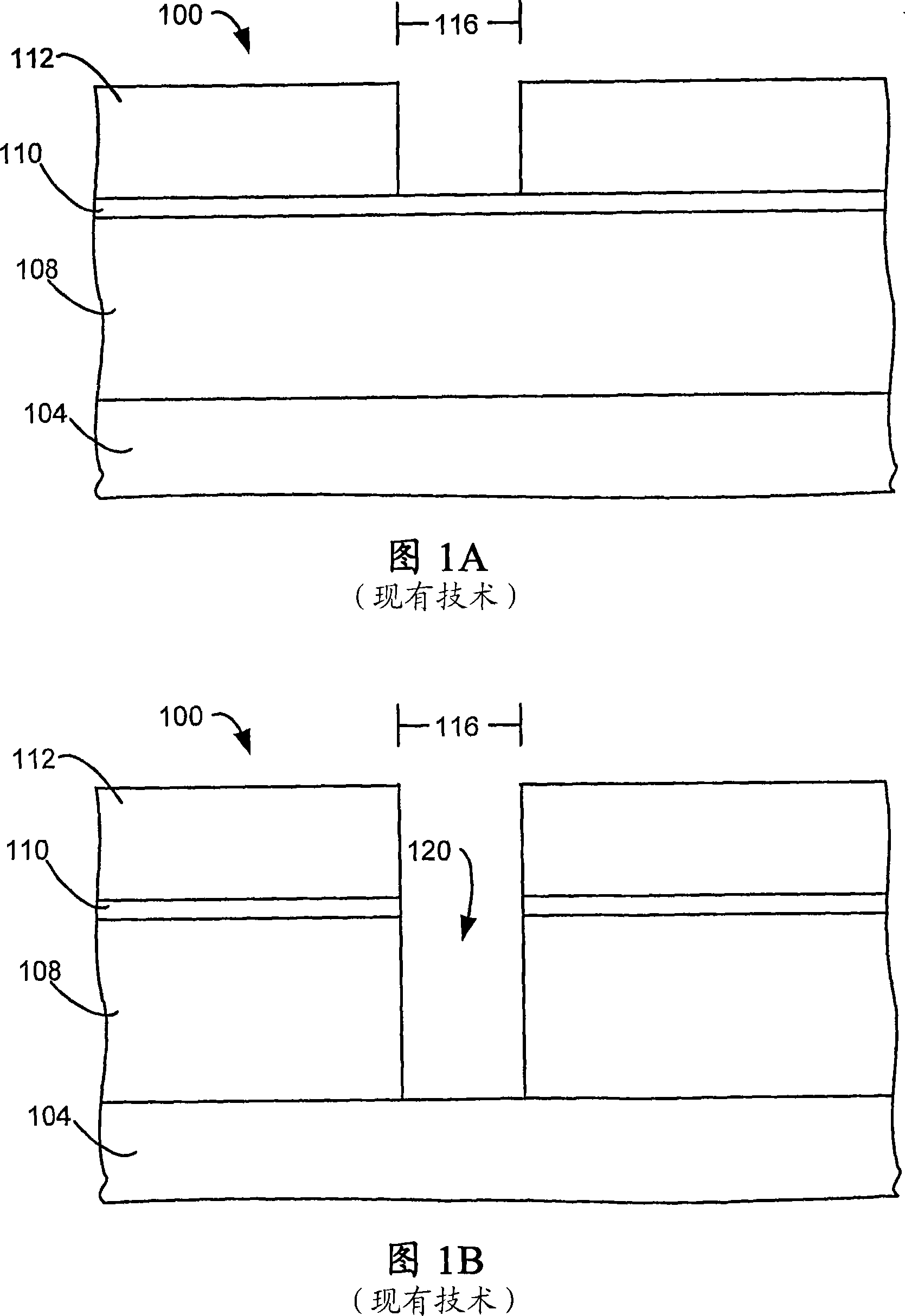
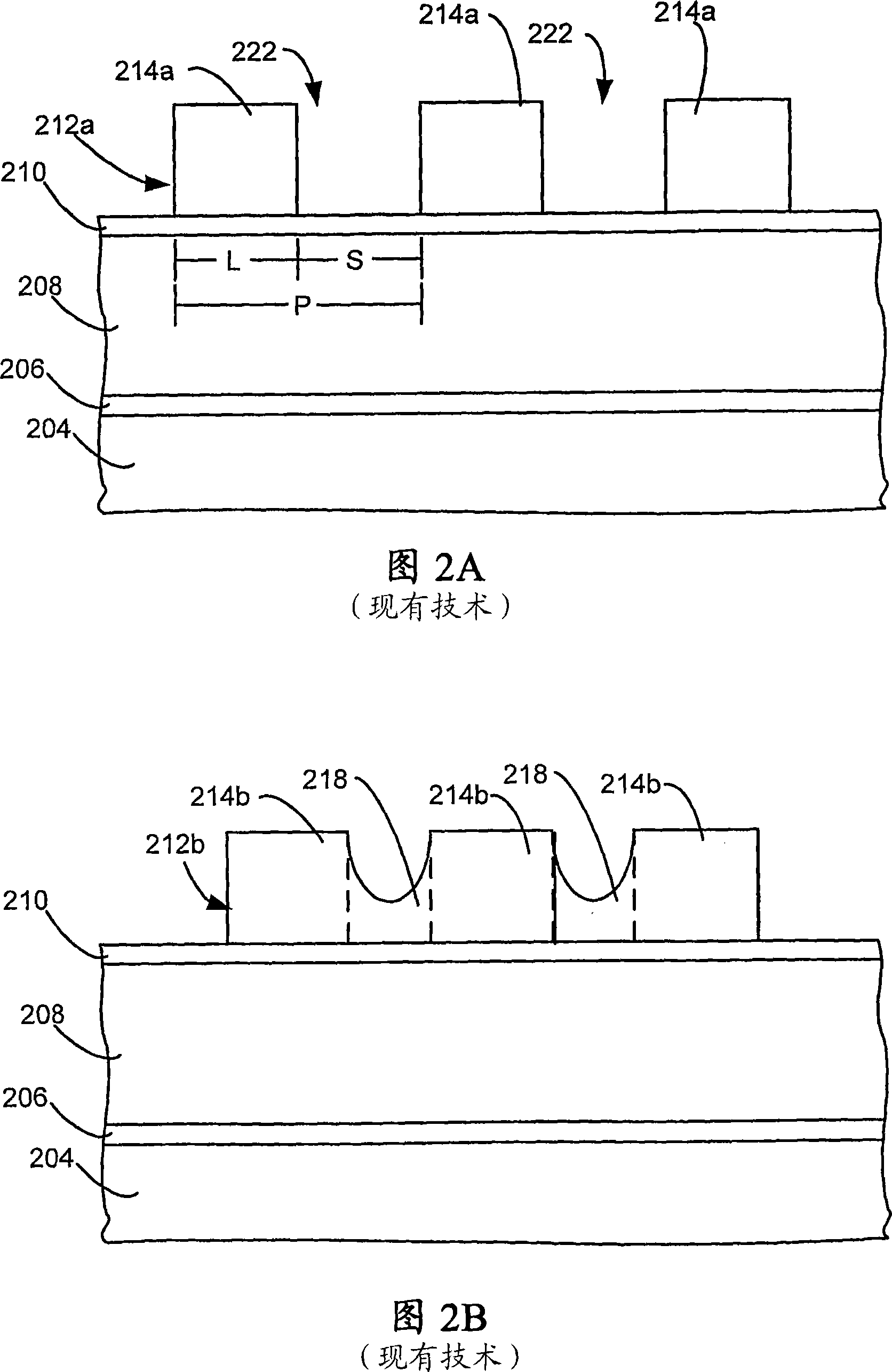
The presence of photoresist residue 218 is caused by too small a space between patterned lines 214b, because it is more difficult to remove residue 218 in a small space
This may limit the density of wires that can be provided

Method used


Image

  • Reticle alignment and overlay for multiple reticle process
  • Reticle alignment and overlay for multiple reticle process
  • Reticle alignment and overlay for multiple reticle process

Examples


example

[0058] Using an example of a system of one embodiment of the present invention, the system 1200 shown in FIG. 12 is used to provide a reticle for a multi-mask etch process and is used to provide verification for shrinkage control rule modifications . A feature layout of the feature arrangement is generated and / or submitted at layout 1204 (step 1104). The reticle layout 1208 in this embodiment produces at least two reticle layouts (step 1108 ) from the feature layout for use in a multi-etch process. The reticle layout requires computer code capable of generating a plurality of reticles from the feature layout and capable of upscaling the feature according to the shrinkage process to be used.

[0059] Shrinkage correction processor 1212 is used to perform shrinkage correction on at least two reticle layouts (step 1112). Shrinkage correction processor 1212 is used to generate reticle data 1216 for at least two reticle layouts with shrinkage correction (step 1116). Other elemen...


PUM


Abstract

A method for generating a plurality of reticle layouts is provided. A feature layout with a feature layout pitch is received. A plurality of reticle layouts are generated from the feature layout where each reticle layout of the plurality of reticle layouts has a reticle layout pitch and where each reticle layout pitch is at least twice the feature layout pitch.

Description

technical field [0001] The present invention relates to the formation of semiconductor devices. Background technique [0002] During semiconductor wafer processing, features of semiconductor devices are defined in the wafer using well-known patterning and etching processes. In these processes, a photoresist (PR) material is deposited on a wafer and then exposed to light filtered by a reticle. The reticle is typically a glass plate formed with a pattern of typical feature geometries that prevent light from passing through the reticle. [0003] After passing through the reticle, the light contacts the surface of the photoresist material. Light changes the chemical composition of the photoresist material, allowing the developer to remove some of the photoresist material. In the case of positive tone photoresist materials, exposed areas are removed, and in the case of negative tone photoresist materials, unexposed areas are removed. The wafer is then etched to remove underly...

Claims


Application Information

Patent Timeline
Patent Type & Authority Applications(China)
IPC IPC(8): G03F7/20H01L21/308
CPCH01L21/0338G03F7/70433G03F7/70466H01L21/0273G03F9/7073H01L23/544H01L2223/54426
Inventor S·M·R·萨贾迪尼古拉斯·布赖特
Owner LAM RES CORP
Features
  • R&D
  • Intellectual Property
  • Life Sciences
  • Materials
  • Tech Scout
  • Unparalleled Data Quality
  • Higher Quality Content
  • 60% Fewer Hallucinations
Learn More