
Bracket valve with internal layer ligule structure and method for knitting bracket

A tongue-shaped structure and mesh stent technology, applied in the field of substitutes for human tissue, can solve the problems of reduced life expectancy, slippage, valve leaflet damage, etc., and achieve the effect of reducing wear and prolonging the service life.

Active Publication Date: 2008-05-07
BEIJING BALANCE MEDICAL
View PDF5 Cites 11 Cited by
  • Summary
  • Abstract
  • Description
  • Claims
  • Application Information

AI Technical Summary

Benefits of technology

The technical effect that this invention solves by reducing strain on certain parts during opening or closing it without causing damage over time.

Problems solved by technology

Technical Problem addressed in this patented technical solution describes how current methods used to treat damaged cardiac muscle often result in complications including dysfunction/failure requiring revision surgeries.

Method used


Image

  • Bracket valve with internal layer ligule structure and method for knitting bracket
  • Bracket valve with internal layer ligule structure and method for knitting bracket
  • Bracket valve with internal layer ligule structure and method for knitting bracket

Examples


Embodiment Construction

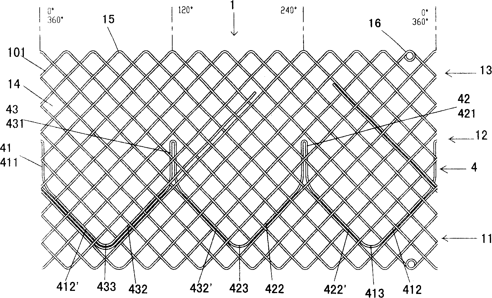
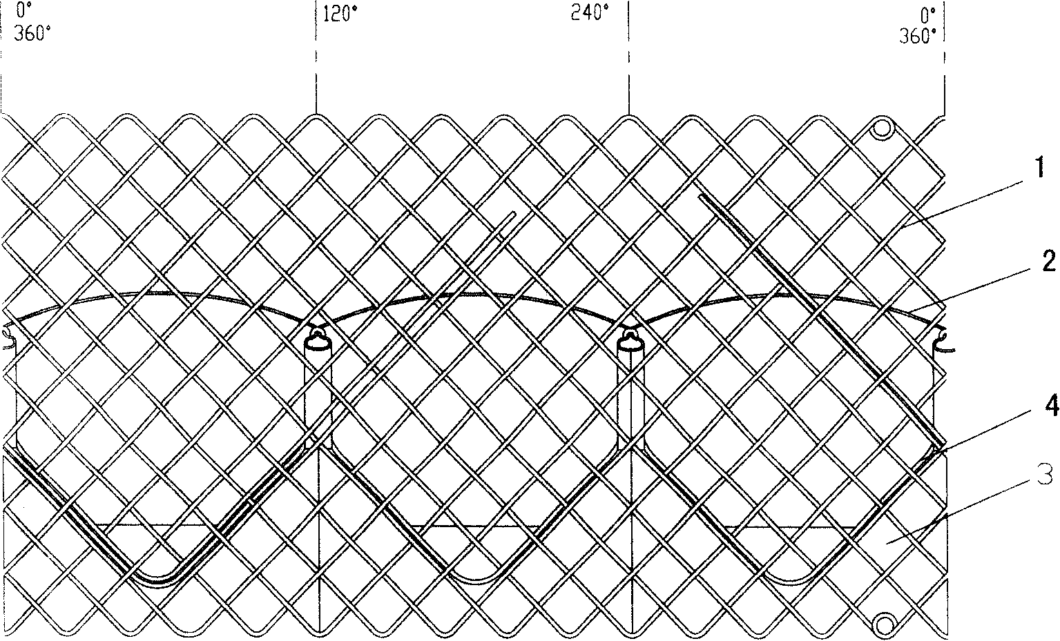
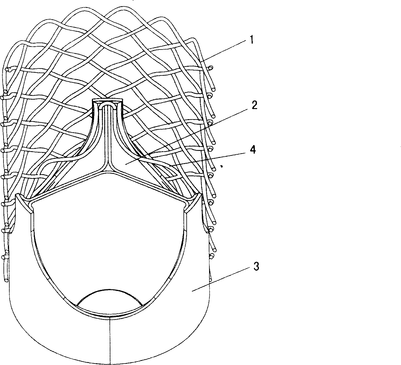
[0064] see figure 1 , referring to the remaining figures, the stent valve with an inner tongue structure of the present invention includes a radially deformable tubular mesh stent body 1 , leaflets 2 , membrane 3 and an inner tongue structure 4 . The inner tongue-shaped structure 4 is connected to the inner side of the stent body 1, and forms a stent with an inner tongue-shaped structure together with the stent body. The inner tongue-like structure 4 contains at least one inner free tongue that can move to the inside of the stent. The inner free tongue constitutes the connecting edge between the valve leaflet 2 and the covering film 3. The leaflet 2 and the covering film 3 are connected to the inner free tongue, or through the inner free tongue. The free tongue is connected with the frame body.

[0065] The tubular mesh stent body in the present invention can be a straight tubular mesh stent, a drum shaped mesh stent with a drum-shaped structure in the middle section, or a ra...


PUM


Abstract

A stent valve includes a tubular netted stent body (1) deformable radially and leaflets (2) and an overlay film (3), and also includes an inner tongue structure (4) connected to the inside of the stent body (1). The inner tongue structure (4) and the stent body (1) cooperatively constitute a stent with an inner tongue structure. The inner tongue structure (4) contains at least one inner free tongue movable to the inside of the stent. The inner free tongues constitute connecting rims of the leaflets (2) and the overlay film (3). The leaflets (2) and the overlay film (3) connect with the inner free tongues, or connect with the stent body (1) via the inner free tongues. The weaving method of the woven stent with an inner tongue structure includes a first weaving and a second weaving.

Description


Claims


Application Information

Patent Timeline
Owner BEIJING BALANCE MEDICAL
Learn More