Device for projecting a pixelated lighting pattern

A technology for lighting equipment and lighting patterns, which is applied in lighting and heating equipment, lighting devices, fixed lighting devices, etc., and can solve problems such as power consumption of data projectors

Active Publication Date: 2008-05-14
SIGNIFY HLDG BV
View PDF1 Cites 14 Cited by
  • Summary
  • Abstract
  • Description
  • Claims
  • Application Information

AI Technical Summary

Problems solved by technology

As such, conventional data projectors tend to be very power hungry devices when used for indoor lighting

Method used


Image

  • Device for projecting a pixelated lighting pattern
  • Device for projecting a pixelated lighting pattern

Examples


Embodiment Construction

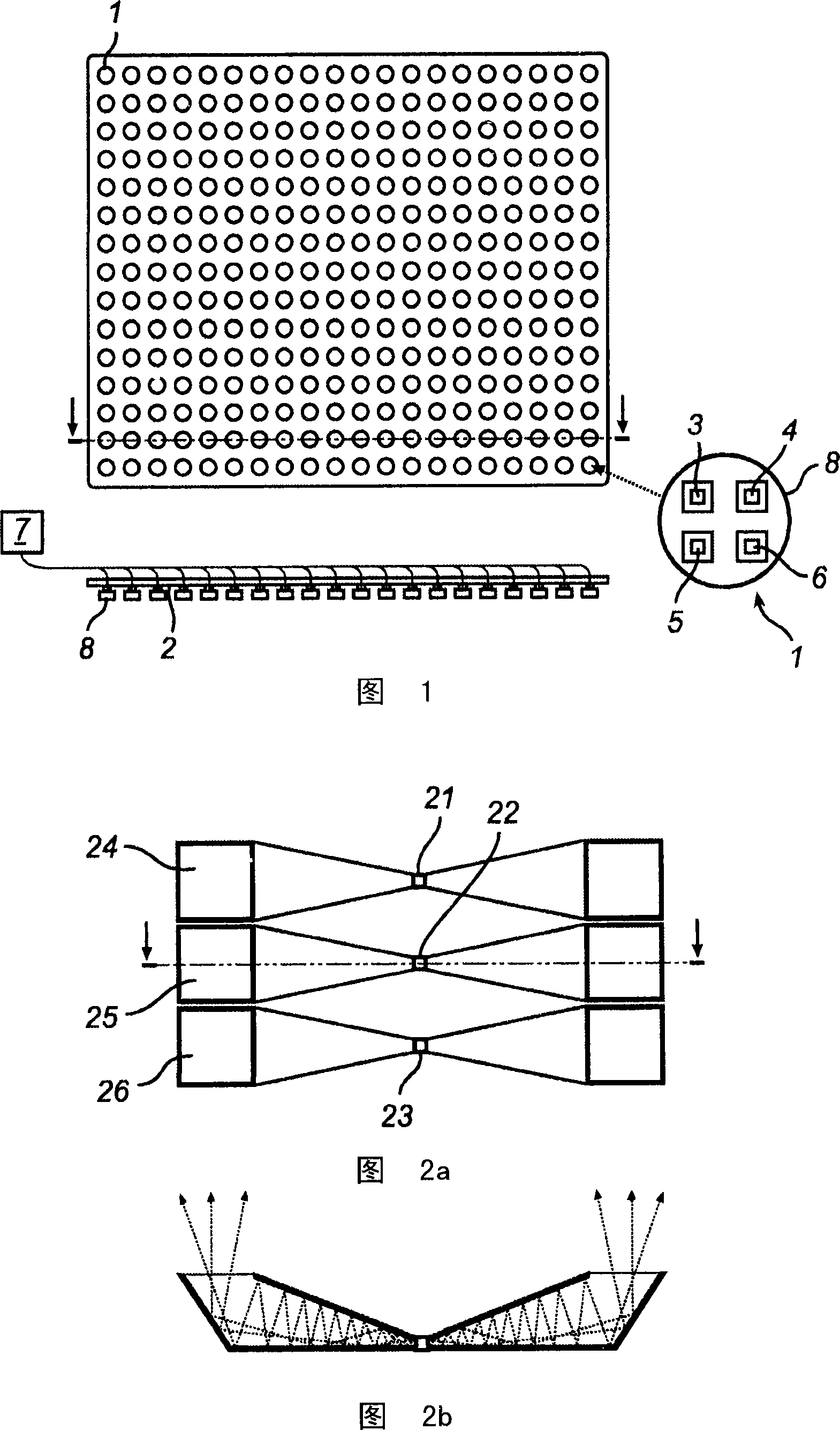
[0029] The exemplary embodiment of the invention shown in Figure 1 comprises a rectangular 20x16 matrix of color and intensity variable lighting units 1 arranged on a substantially rectangular panel 2 of size 2x1.6m . The lighting units were arranged in a rectangular grid with a pitch of 10 cm.

[0030] Each lighting unit comprises a group of four light emitting diodes, namely red diodes 3 , blue diodes 4 , green diodes 5 and white diodes 6 .

[0031] Each of these diodes is connected to an LED controller 7 capable of independently controlling the intensity of light emitted by each LED in each individual lighting unit 1 .

[0032] A collimator 8 is arranged on the LEDs 3, 4, 5, 6 to collimate the light from each LED into a narrow beam with a collimation angle of about 8°.

[0033] These collimators are arranged to project light substantially in the middle of the normal to the panel surface.

[0034] When the light beams from each lighting unit 1 are narrowly collimated and ...


PUM


Abstract

A lighting device is provided for projecting a pixelated lighting pattern to be viewed onto a surface facing said device is provided. The device comprises a plurality of independently controllable lighting units (1), each lighting unit comprising at least one light- emitting diode (3, 4, 5, 6), and a controller (7) for controlling the emission of light from said lighting units. A device according to the present invention allows ambient illumination of a surface and projection of images and patterns.

Description

technical field [0001] The present invention relates to a lighting device for projecting an observed pixelated lighting pattern on a surface facing the lighting device, the lighting device comprising a plurality of lighting units and means for controlling the light from these lighting units For the emission controller, each lighting unit includes at least one light emitting diode. Background technique [0002] Lighting devices based on light emitting diodes are usually designed for indoor lighting, such as in offices, homes, shops, cars and airplanes. [0003] Fluorescent tubes and incandescent lamps have been used as light sources for these lighting devices. [0004] Recently, light emitting diodes (LEDs) have been proposed as light sources for such lighting devices. Lighting fixtures based on light-emitting diodes are attractive because light-emitting diodes typically have a much longer lifespan than fluorescent and incandescent light bulbs. Also, LEDs consume less powe...

Claims


Application Information

Patent Timeline
Patent Type & Authority Applications(China)
IPC IPC(8): G02B26/08H05B37/02
CPCG09F19/18F21Y2105/001H05B33/0842H05B33/0857H05B37/02F21Y2101/02F21S8/06F21Y2105/10F21Y2115/10H05B45/00H05B45/20H05B47/10F21Y2105/16H05B47/175
Inventor P·A·杜恩H·J·科尼利森H·扎恩M·西肯斯J·E·德夫里斯R·A·H·布利恩
Owner SIGNIFY HLDG BV
Why Eureka
Try Eureka