
Illumination device

a technology of a lens body and a slit, which is applied in the direction of lighting device details, lighting and heating apparatus, instruments, etc., can solve the problems of difficult to reduce the size and thickness of the optical element, low mass-productivity, and bulky lens body, and achieve the effect of easy mass-production

Active Publication Date: 2016-03-17
MINEBEAMITSUMI INC
View PDF8 Cites 3 Cited by
  • Summary
  • Abstract
  • Description
  • Claims
  • Application Information

AI Technical Summary

Benefits of technology

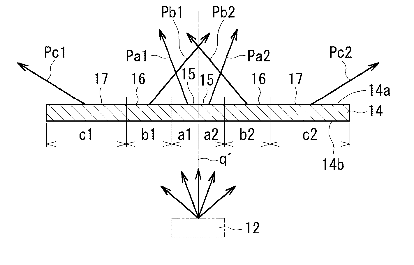
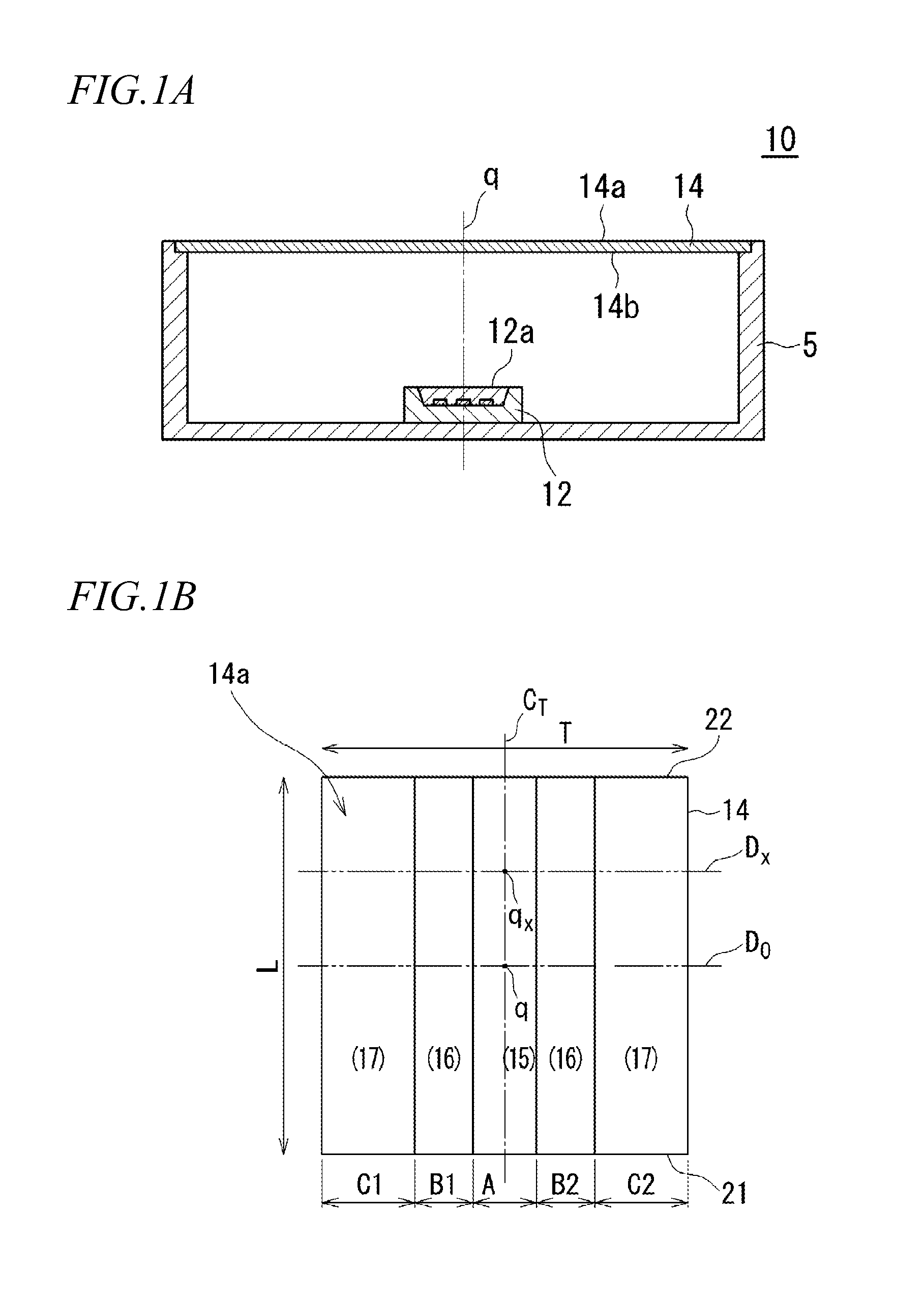
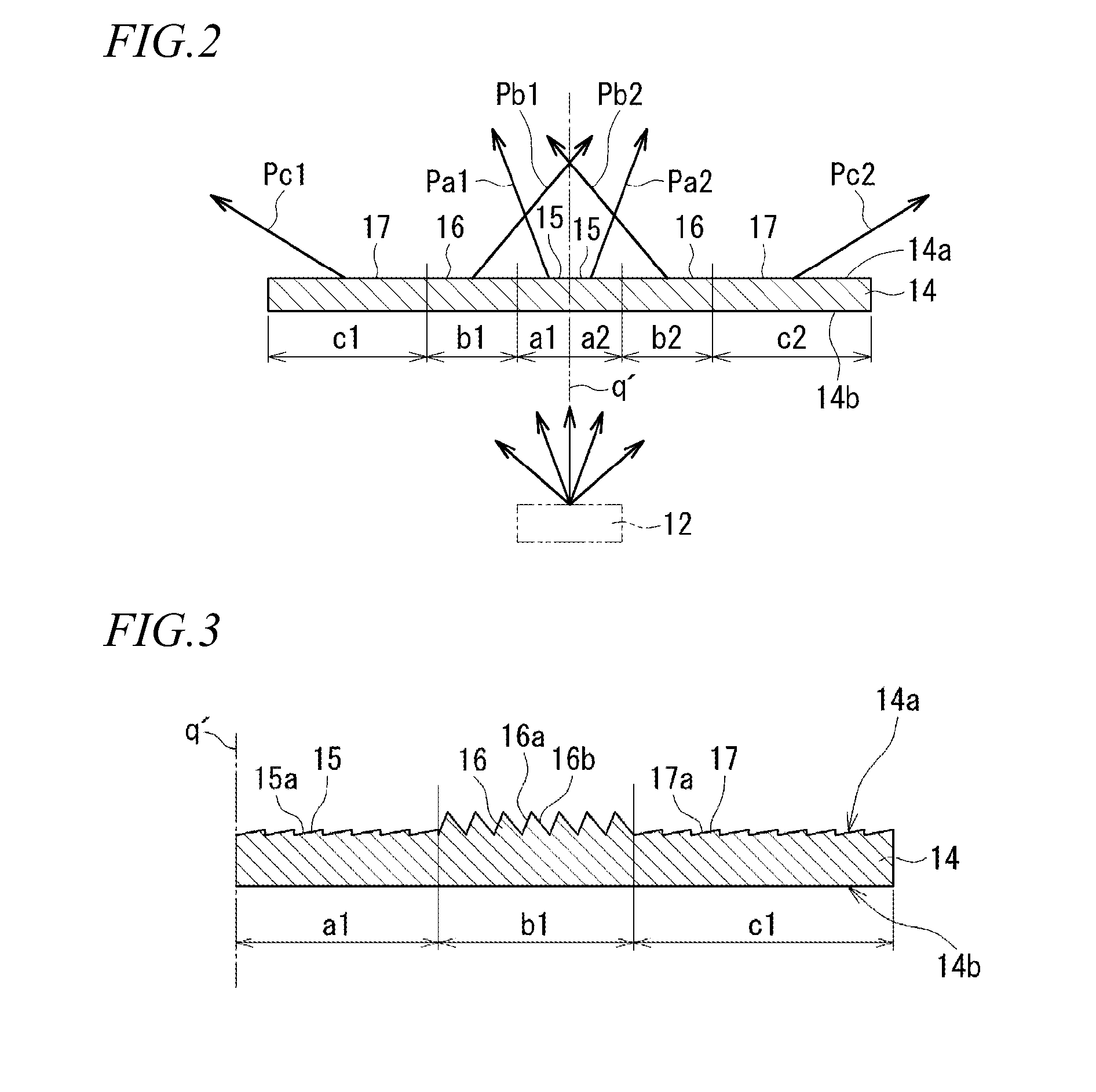
The present invention provides an illumination device that can achieve the batwing light distribution using a thin and easily mass-produced plate-like optical member. The device can be used as a street light and achieve the asymmetric light distribution for one direction and the batwing light distribution for a direction orthogonal to one direction. The device includes a light source unit and the optical member which has a first refractive prism and a reflective prism. The optical axis of the light source unit passes through the region where the first refractive prism is placed. The first refractive prism and the reflective prism are designed to cause incident light to travel to sides opposite to each other with respect to the optical axis.

Problems solved by technology

However, in the illumination device disclosed in JP-A-2014-093233, a bulky lens body is used as the optical element for controlling the light distribution of the illumination light.
Therefore, it may be difficult to reduce the size and thickness of the optical element, eventually, the illumination device.
Further, since an emitting surface of the lens body is configured by a plurality of complex three-dimensional curved surface, there may be a problem that the mass-productivity (productivity) is low.

Method used


Image

  • Illumination device
  • Illumination device
  • Illumination device

Examples


Embodiment Construction

[0025]The following modes (1) to (8) described below illustrate the exemplary configurations of the present invention. In order to facilitate the understanding of various configurations of the present invention, each mode is described separately. Each mode is not intended to limit the technical scope of the present invention. Some of the components of each mode can be replaced and omitted, and other components can be added thereto, in consideration of the best mode for carrying out the invention. These can be also included in the technical scope of the present invention.

[0026](1) There is provided an illumination device including: a light source unit; and an optical member having a plate-like shape and disposed in front of the light source unit. The optical member includes a first refractive prism having a function of refracting light, and a reflective prism disposed on an outer side of the first refractive prism and having a function of reflecting light. An optical axis of the ligh...


PUM


Abstract

An illumination device includes: a light source unit; and an optical member having a plate-like shape and disposed in front of the light source unit, wherein the optical member includes a first refractive prism having a function of refracting light, and a reflective prism disposed on an outer side of the first refractive prism and having a function of reflecting light, wherein an optical axis of the light source unit is configured to pass through a region in which the first refractive prism is disposed, wherein the first refractive prism is configured to cause an incident light to travel to a side opposite to the optical axis, and wherein the reflective prism is configured to cause an incident light to travel to the optical axis side.

Description

BACKGROUND[0001]1. Field of the Invention[0002]The present invention relates to an illumination device. In particular, the present invention relates to an illumination device for controlling the light distribution of light emitted from a light source by using an optical element.[0003]2. Description of the Related Art[0004]Generally, in an illumination device, various light distribution characteristics are required depending on installation environment in which the illumination device is installed. For example, for a street light (road light) of a type that is installed to stand beside a road, light distribution characteristics different from each other are often required in a road traffic direction and a road width direction orthogonal to the road traffic direction. Typically, in the road traffic direction, a so-called batwing light distribution is required for the purpose of uniformly illuminating a wide range. On the other hand, in the road width direction, an asymmetric light dis...

Claims


Application Information

Patent Timeline
IPC IPC(8): F21V13/04
CPCF21V13/04F21V5/02F21V7/0091G02B5/045G02B19/0028G02B19/0066
Inventor WATANABE, TAKEFUMI
Owner MINEBEAMITSUMI INC
Learn More