Sliding arrow stabilizer

a stabilizer and arrow technology, applied in the direction of arrows, weapons, projectiles, etc., can solve the problems of inconvenient use, inconvenient use, and inability to adjust the stabilizer, so as to prevent further rearward travel of the stabilizer, eliminate the interference at the arrow rest, and eliminate the inconsistencies and costs associated.

Active Publication Date: 2008-02-19
DESERT DYNAMIC RES
View PDF21 Cites 50 Cited by
  • Summary
  • Abstract
  • Description
  • Claims
  • Application Information

AI Technical Summary

Benefits of technology

[0018]The present invention provides a field replaceable sliding stabilizer that eliminates the inconsistencies and costs associated with traditional multi-piece glue on fletching systems. Further, an arrow comprising a stabilizer consistent with the present invention eliminates interference at the arrow rest caused by conventional fletching and a conventional bow.
[0019]A stabilizer consistent with the present invention may easily be mass-produced and is capable of providing high accuracy devices with highly repetitive results in use. Such a stabilizer may comprise a plurality of projections or “fingers” that aid in the operation of the stabilizer by creating a friction or interference fit between the arrow shaft and the stabilizer during slideable engagement therebetween. A stabilizer consistent with the present invention may be particularly shaped or otherwise adapted to provide additional aerodynamic features, e.g., impact force on the target or other such flight characteristics. Further, two or more stabilizers may be disposed along the shaft of an arrow, e.g., at the forward tip to prevent instability caused by the use of exotic or poorly balanced arrows.
[0020]Further, the present invention provides an arrow having improved aerodynamic characteristics, resulting in increased flight stability, speed, and accuracy. An arrow consistent with the present invention requires no feathers or traditional fletching, instead utilizing a sliding aerodynamic stabilizer that is slid or mounted over the front or rear of the arrow shaft, and the arrow travels through the stabilizer until it is positioned on the arrow at a provided stop, after which the stabilizer flies the arrow in a conventional manner. Since an arrow consistent with the present invention may comprise a short cross section, flight stability is less impacted by cross wind drift and wobble. Further, since the arrow requires no fixed fletching attached thereto, the arrow may have a higher acceleration rate due to a reduced mass that has to be initially accelerated by the bow.

Problems solved by technology

This process is time consuming and introduces inconsistencies in spacing and angles.
Moreover, polluting and toxic chemicals are often required to clean the arrow shaft prior to gluing.
Further, conventionally fletched arrows are easily damaged in the field or while in storage.
When damaged, conventional fletching is normally not considered field replaceable and can be difficult to repair.
Finally, prior art stabilizing methods require the fletching to pass over and / or through the arrow rest causing possible interference with the rest, thus imposing certain design limitations.
Arrow rests may interfere with the flight of an arrow through inadvertent contact therewith, thereby adversely affecting flight performance, as well as damaging the fletching through such contact.
While fall-away or offset rests must often be used to reduce the incidence of contact between the arrow rest and the fletching of an arrow, such rests can be expensive and do not resolve other above-mentioned problems associated with fletching.
Deficiencies of this solution, however, include a significantly increased drag problem, excessive length, and failure to resolve the interference problem.

Method used


Image

  • Sliding arrow stabilizer
  • Sliding arrow stabilizer
  • Sliding arrow stabilizer

Examples


Embodiment Construction

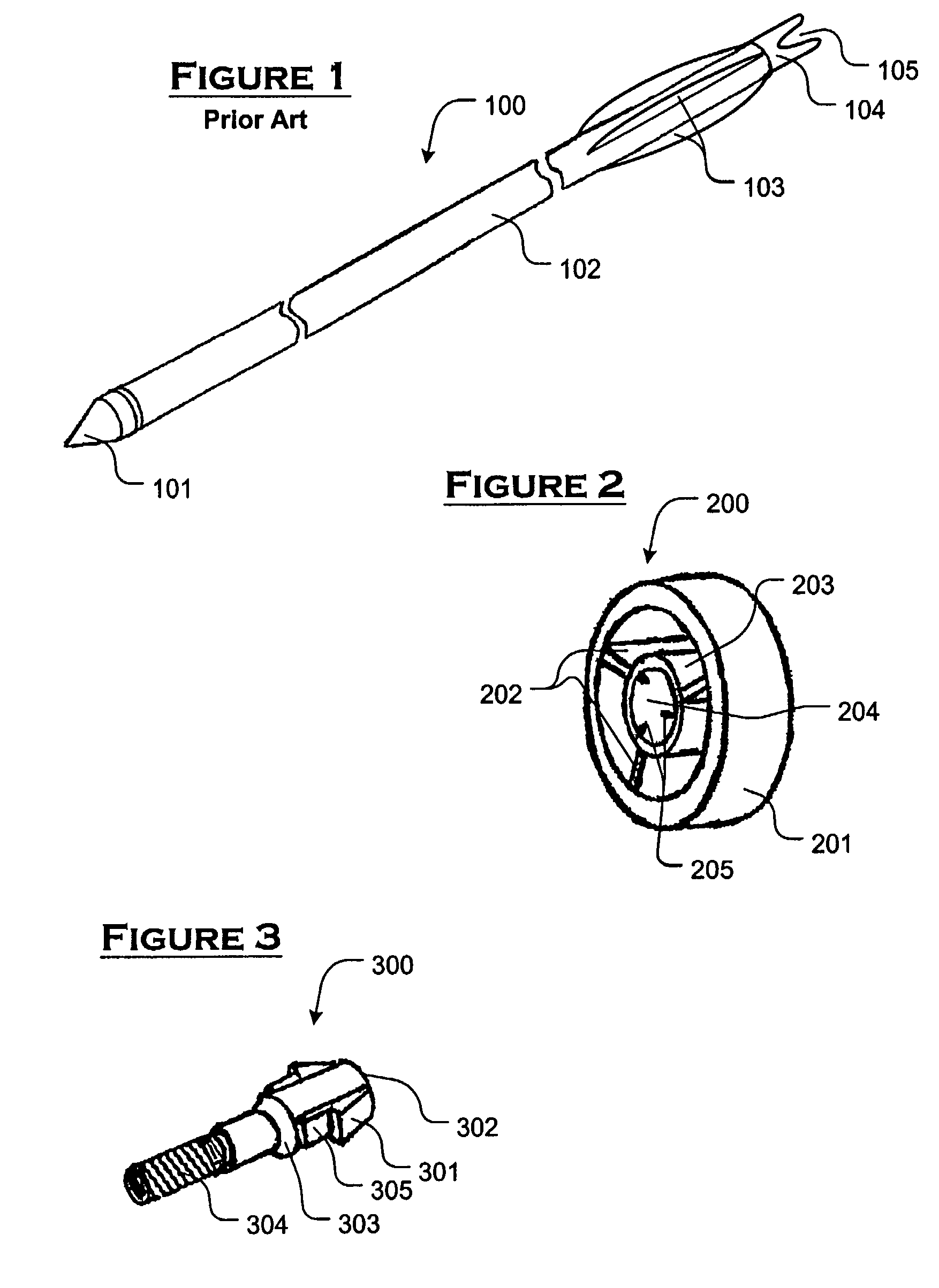
[0030]As illustrated in FIG. 1, a conventional arrow 100 comprises a tip 101, a shaft 102, and a prior art stabilization system comprising a plurality of fins 103 as fletching. The fins 103 are fixed to the shaft 102, e.g., by gluing, and are easily damaged or lost through contact with other surfaces, e.g., with the bow used to launch the arrow 100, with butt material (backing, bales, or dirt designed to stop and hold arrows) of a paper target, or with a game animal. The trailing end of the arrow 100 may comprise a recess (not shown) formed therein for engagement (e.g., via a plurality of threads) with a nock 104 that secures the arrow 100 in place before launch, e.g., by disposing a bowstring (not shown) within a notched area 105 of the nock 104.

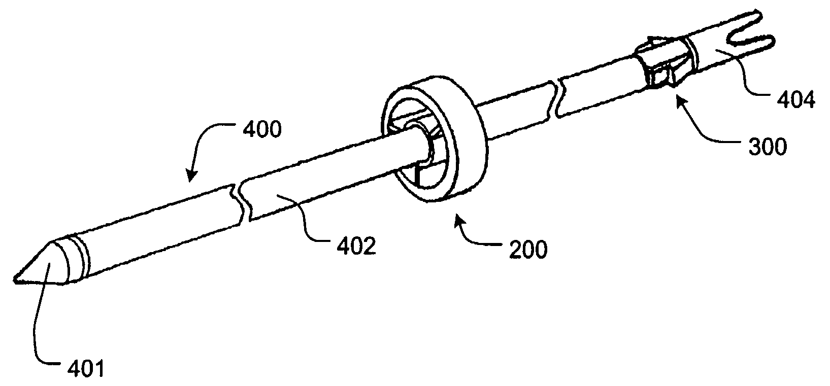
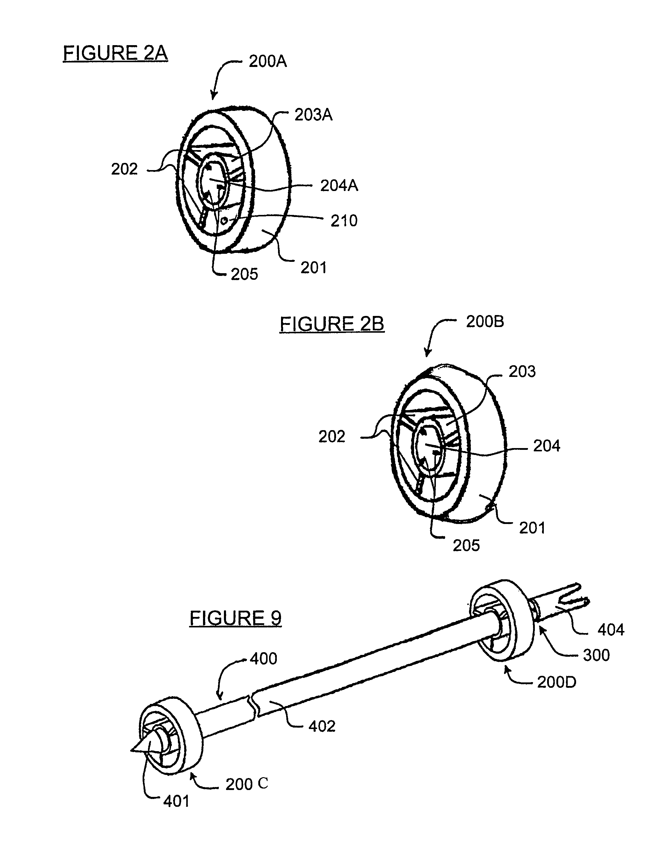
[0031]Turning now to FIG. 2, an exemplary arrow stabilizer 200 in one embodiment of the present invention is illustrated. This “sliding” stabilizer is field replaceable, reduces assembly labor cost, and significantly improves the stability ...


PUM


Abstract

An improved arrow and sliding stabilizer therefor are provided. The sliding stabilizer is used for stabilizing arrow flight, instead of fixed or glued tail feathers, vanes or other fletching. The invention improves current projectile technology with reduced assembly labor cost, the elimination of bow clearance issues, improved accuracy with the consistent production of the sliding stabilizer, easy replacement of the stabilizer in the field, and improved arrow storage. A sliding stabilizer is designed to slide along the shaft of an arrow and comprises an annular wing and a plurality of fins. In use, the stabilizer is positioned at the front of the arrow prior to launch, and the arrow slides quickly through the stabilizer until secured at a stop position at or near the trailing end of the arrow.

Description

CROSS REFERENCE TO RELATED APPLICATION[0001]This application claims the benefit of U.S. Provisional Patent Application No. 60 / 315,165, filed on Aug. 28, 2001, the teachings of which are incorporated herein by reference.BACKGROUND OF THE INVENTION[0002]1. Field of the Invention[0003]This invention relates generally to a stabilizer for a projectile, and more particularly, to a stabilizer for the flight of an arrow in the field of archery.[0004]2. Definitions[0005]“Fletching” is a generic term used to describe the fins of an arrow that guide and stabilize the arrow during flight. These fins, when made from natural feathers, are commonly referred to collectively as “fletching”, comprising individual “fletches.” When made from plastic or other man-made materials, these fins are called “vanes.” In the present application, the terms “fletching,”“feathers,”“vanes,” and “fins” are employed throughout when describing fins of any type and are used interchangeably.[0006]“Nock” is a generic term...

Claims


Application Information

Patent Timeline
Patent Type & Authority Patents(United States)
IPC IPC(8): F42B6/04F42B6/06F42B10/12F42B10/18
CPCF42B6/06F42B10/12F42B10/18
Inventor MORRIS, PAULPETERSON, LARRY
Owner DESERT DYNAMIC RES
Why Eureka
Try Eureka