Camera module aligning method

A camera module and lens technology, which is used in metal processing, workpiece clamping devices, metal processing equipment, etc., can solve problems such as deviation of results, no suggestion, manual adjustment errors, etc., to eliminate inconsistencies, adjust speed quickly, and improve The effect of assembly efficiency

Active Publication Date: 2018-09-28
深圳市策维软件技术有限公司
View PDF8 Cites 12 Cited by
  • Summary
  • Abstract
  • Description
  • Claims
  • Application Information

AI Technical Summary

Problems solved by technology

[0003] Many manufacturers focus on the alignment and assembly of mobile phone camera modules. The traditional method is mainly through manual alignment of mobile phone modules. The quality of the same batch of products is different, and the labor is easy to be tired, the efficiency is low, there is no competitive advantage, and it is not suitable for modern production methods
In recent years, there have been more device methods for active alignment of modules. CN201720999468.5 proposed a multi-axis active alignment device, but did not propose a specific algorithm based on the device to achieve a specific adjustment method; CN2016106998589.6 provides A multi-axis alignment method is proposed, but when adjusting the center of the lens and the center of the image sensor, multiple image local measurement areas must be preset, which requires stricter requirements on the details of the image target map, and the operation of adjusting the center of the lens and the tilt angle, etc. Before the stage, it is necessary to manually take multiple photos of the image test version to record the calibration graphic position. Manual participation undoubtedly introduces image subjective evaluation standards and manual adjustment errors during manual participation, resulting in deviations in the final results.

Method used


Image

  • Camera module aligning method
  • Camera module aligning method
  • Camera module aligning method

Examples


Embodiment Construction

[0021] The present invention will be further described below in conjunction with the accompanying drawings and embodiments.

[0022] refer to Figures 1 to 3 , in a preferred embodiment: the specific steps of the alignment method of the camera module (hereinafter referred to as the module for convenience of description) are as follows:

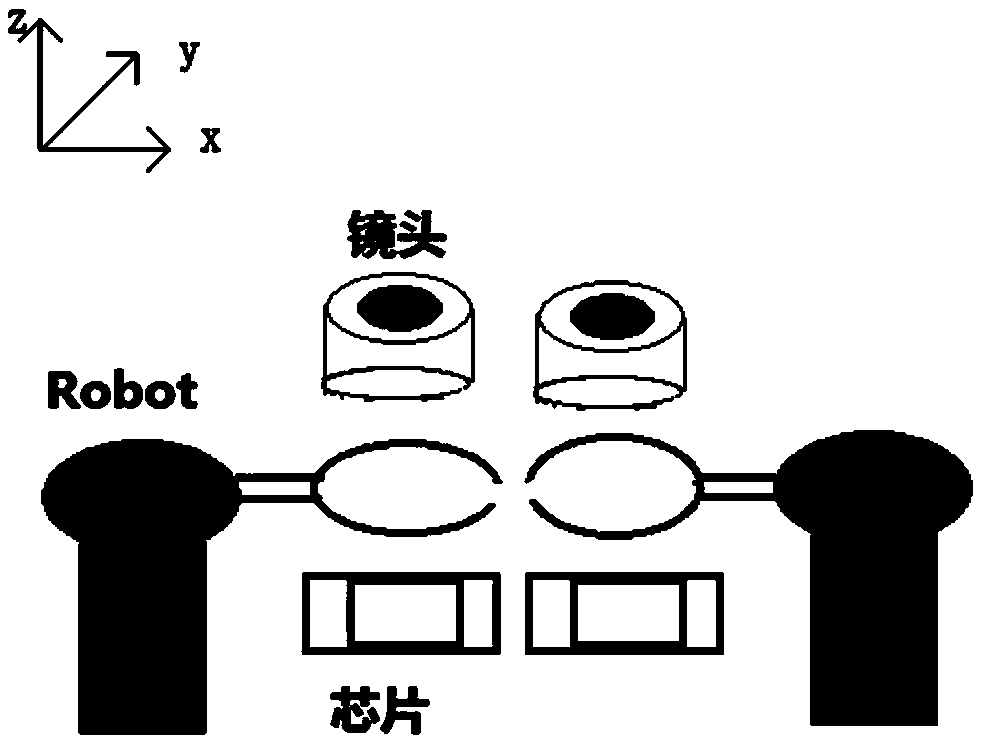
[0023] Step 1: Loosen the gripper of the six-axis robot, use the motion mechanism to send the lens of the module to the middle of the gripper of the six-axis robot, close the gripper, clamp the lens, and use the PLC motion control mechanism to send the sensor chip to the gripper of the six-axis robot Below the claw, the robot adjusts the lens to the initial adjustment position above the sensor chip;

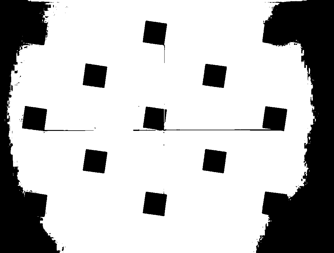
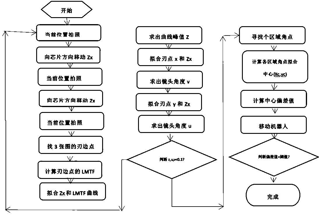
[0024] Step 2: Trigger the module at the initial adjustment position or the adjusted new position to take the target image photo P1, adjust the Z axis of the robot to move it down the distance Zx (x=1,2,3,...), trigger The module takes the phot...


PUM


Abstract

The invention discloses a camera module aligning method which regulates a robot in a multi-station parallel mode in a three-dimensional space, improves module assembly efficiency, and can quickly finda proper position with clearest imaging of a camera lens and a sensor chip through an approach method of the lens one-end type bisection method strategy. According to a simple target figure, different area knife-edge points are quickly obtained by a regional Laplace gray mask method to calculate an LMFT value, a z value which corresponds to a definition peak value is obtained through polynomial curve fitting, characteristics of the target figure are delicately utilized to obtain an angular point mean value of different areas, and the camera lens is regulated according to image center deviation, so that the optical axis center of the camera lens is quickly superposed with the center of a sensor, and therefore, quality evaluation indexes of a finished product module do not need to introducein advance throughout the process for detecting definition of semi-finished products, inconsistency of image subjective evaluation is eliminated, regulating speed is high, and z, u and v can be effectively converged.

Description

technical field [0001] The invention relates to the field of camera module assembly, in particular to a camera module alignment method. Background technique [0002] With the advancement of society and the development of technology, high-end smartphones have become the standard equipment for people, especially young people, which is promoting the popularity of the high-end mobile phone industry. Mobile phone camera modules occupy the highest interest chain in the high-end mobile phone market point. [0003] Many manufacturers focus on the alignment and assembly of mobile phone camera modules. The traditional method is mainly through manual alignment of mobile phone modules. The quality of the same batch of products is different, and the labor is easy to be tired, the efficiency is low, there is no competitive advantage, and it is not suitable for modern production methods. In recent years, there have been more device methods for active alignment of modules. CN201720999468....

Claims


Application Information

Patent Timeline
Patent Type & Authority Applications(China)
IPC IPC(8): B25B11/00B23P19/00
CPCB23P19/00B25B11/00
Inventor 郭鹏洲吴战胜高海涛
Owner 深圳市策维软件技术有限公司
Why Eureka
Try Eureka